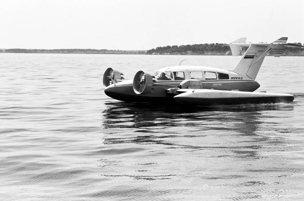
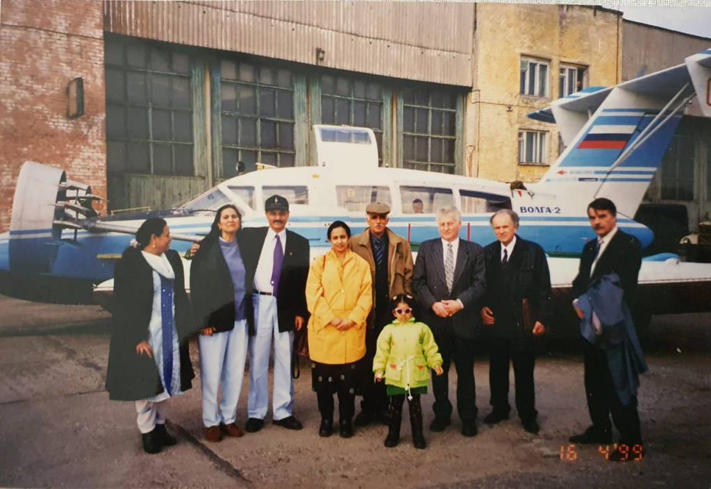
In 1998/99 I had the unique opportunity to take two flights in Volga-2 ekranoplan produced by Volga Shipyard in Nizhniy Novgorod, Russia. The small ekranoplan for non-military use like the eight seat Volga-2 were developed as small water taxis. They were part of the ground-effect vehicle (GEV), also called a wing-in-ground-effect (WIGE), ground-effect craft, wingship, flarecraft or ekranoplan (Russian for “screenglider”). These are vehicles that are able to move over the surface by gaining support from the reactions of the air against the surface of the earth or water. Typically, it is designed to “fly” over a level surface (usually over the sea/river/lake) by making use of ground effect, the aerodynamic interaction between the moving wing and the surface below. Some models can operate over any flat area such as frozen lakes or flat plains similar to a hovercraft.
Ground Effect Aerodynamics
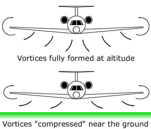
An aerofoil passing through air increases air pressure on the underside, while decreasing pressure across the top. The high and low pressures are maintained until they flow off the ends of the wings, where they form vortices which in turn are the major cause of lift-induced drag—normally a large portion of the drag affecting an aircraft. The higher the aspect ratio of the wing (that is, the longer and skinnier it is), the less induced drag created for each unit of lift and the greater the efficiency of the particular wing. This is the primary reason gliders have long and skinny wings.
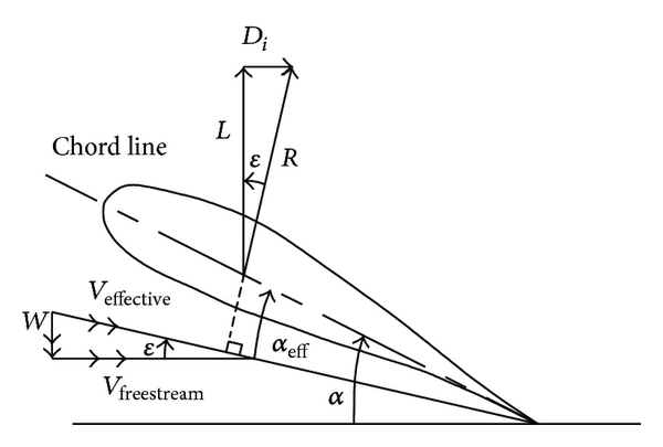
A ground-effect vehicle (GEV) needs some forward velocity to produce lift dynamically and the principal benefit of operating a wing in ground effect is to reduce its lift-dependent drag. The basic design principle is that the closer the wing operates to an external surface such as the ground, when it is said to be in ground effect, the more efficient it becomes. Placing the same wing near a surface such as the water or the ground has the effect of greatly increasing the aspect ratio, but without having the complications associated with a long and slender wing, so that the short stubs on a GEV can produce just as much lift as the much larger wing on a transport aircraft, though it can do this only when close to the earth’s surface. Once sufficient speed has built up, some GEVs may be capable of leaving ground effect and functioning as normal aircraft until they approach their destination. The distinguishing characteristic is that they are unable to land or take off without a significant amount of help from the ground effect cushion, and cannot climb until they have reached a much higher speed.
For fixed-wing aircraft, ground effect is the reduced aerodynamic drag that an aircraft’s wings generate when they are close to a fixed surface. Reduced drag when in ground effect during take-off can cause the aircraft to “float” whilst below the recommended climb speed. The pilot can then fly just above the runway while the aircraft accelerates in ground effect until a safe climb speed is reached. If the wing is designed properly, the lifting surface near ground generates higher lift at smaller ground clearances. However, the drag decreases with decreasing ground clearance for span-dominated GE. Endplates on small aspect ratio (AR) wing result in the reduction of the tip vortex and development of a substantial rise in the lift and lift-to-drag ratio. These would also make a small deviation of height stability at different ground clearances and angle of attacks, which can reduce the height stability. For acceptable stability of a WIG craft, the centre of gravity should be close to the height of aerodynamic centre. The improvement of wing can increase the range and endurance of flight and decrease the fuel consumption and CO2 emission.
Wing Stall in Ground Effect
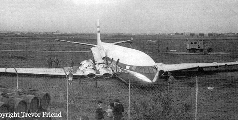
The stalling angle of attack is less in ground effect, by approximately 2-4 degrees, than in free air. When the flow separates there is a large increase in drag. If the aircraft over-rotates on take-off at too low a speed the increased drag can prevent the aircraft from leaving the ground. Two de Havilland Comets overran the end of the runway after over-rotating. Loss of control may occur if one wing tip stalls in ground effect. During certification testing of the Gulfstream G650 business jet the test aircraft rotated to an angle beyond the predicted IGE stalling angle. The over-rotation caused one wing-tip to stall and an un-commanded roll, which overpowered the lateral controls, led to loss of the aircraft.
Rotorcraft
When a hovering rotor is near the ground the downward flow of air through the rotor is reduced to zero at the ground. This condition is transferred up to the disc through pressure changes in the wake which decreases the inflow to the rotor for a given disk loading, which is rotor thrust for each square foot of its area. This gives a thrust increase for a particular blade pitch angle. Or, alternatively, the power required for a thrust is reduced. For an overloaded helicopter that can only hover in ground effect (IGE) it may be possible to climb away from the ground by translating to forward flight first while in ground effect. The ground effect benefit disappears rapidly with speed but the induced power decreases rapidly as well to allow a safe climb. Some early underpowered helicopters could only hover close to the ground. Ground effect is at its maximum over a firm, smooth surface.

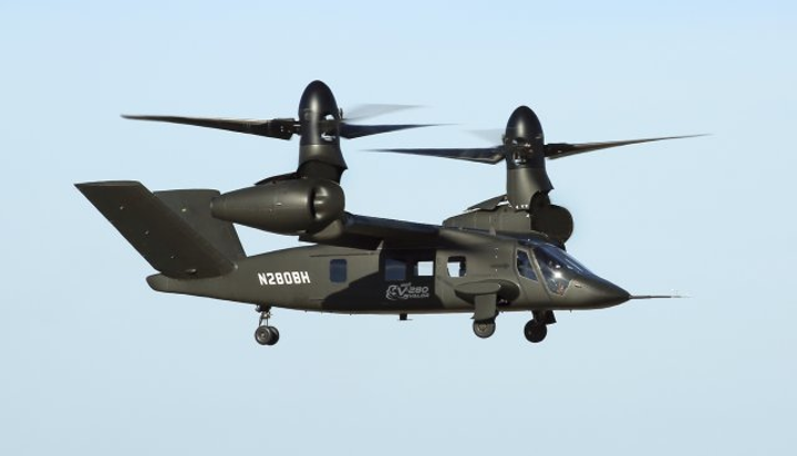
For rotorcraft, ground effect results in more power being available during hovering which allows heavier weights to be lifted. Helicopter pilots are provided with performance charts which show the limitations for hovering their helicopter IGE and out of ground effect (OGE). For fan- and jet-powered VTOL aircraft, ground effect when hovering can cause suck-down and fountain lift on the airframe and loss in hovering thrust if the engine sucks in its own exhaust gas, which is known as hot gas ingestion (HGI).
VTOL Aircraft
There are two effects inherent to VTOL aircraft operating at zero and low speeds IGE, suck-down and fountain lift. A third, HGI, may also apply to fixed-wing aircraft on the ground in windy conditions or during thrust reverser operation. How well, in terms of weight lifted, a VTOL aircraft hovers IGE depends on suck-down on the airframe, fountain impingement on the underside of the fuselage and HGI into the engine. Suck-down works against the engine lift as a downward force on the airframe. Fountain flow works with the engine lift jets as an upwards force. HGI reduces the thrust generated by the engine. Suck-down is the result of entrainment of air around aircraft by lift jets when hovering. It also occurs in free air (OGE) causing loss of lift by reducing pressures on the underside of the fuselage and wings. Enhanced entrainment occurs when close to the ground giving higher lift loss. Fountain lift occurs when an aircraft has two or more lift jets. The jets strike the ground and spread out. Where they meet under the fuselage they mix and can only move upwards striking the underside of the fuselage. How well their upward momentum is diverted sideways or downward determines the lift. Fountain flow follows a curved fuselage underbody and retains some momentum in an upward direction so less than full fountain lift is captured unless Lift Improvement Devices are fitted. HGI reduces engine thrust because the air entering the engine is hotter than ambient.
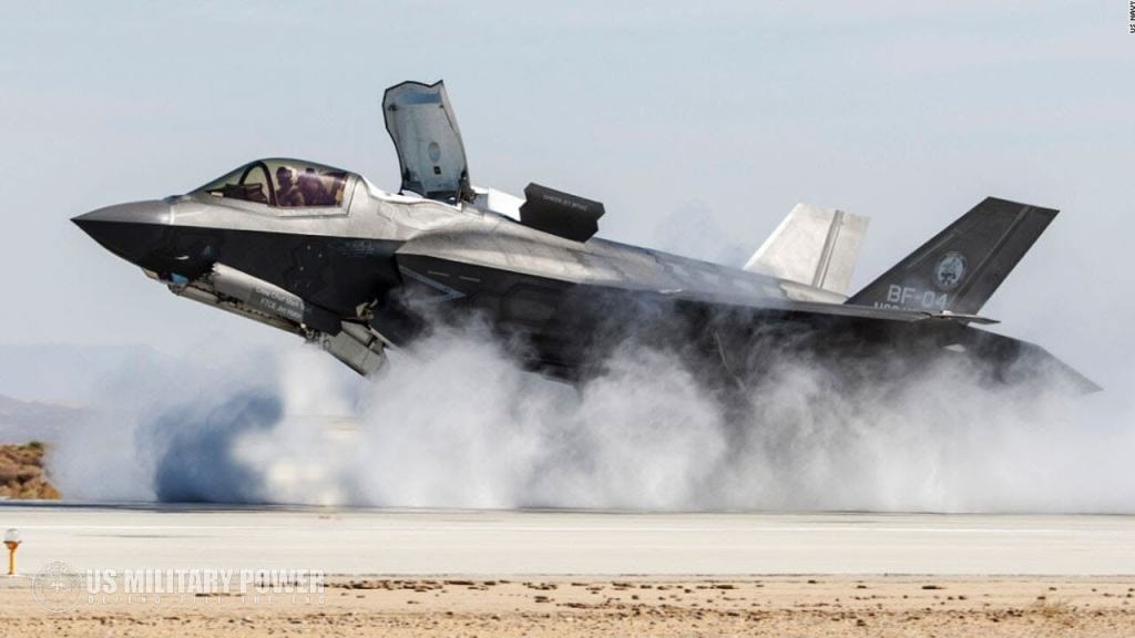
Early VTOL experimental aircraft operated from open grids to channel away the engine exhaust and prevent thrust loss from HGI. The Bell X-14, built to research early VTOL technology, was unable to hover until suck-down effects were reduced by raising the aircraft with longer landing gear legs. It also had to operate from an elevated platform of perforated steel to reduce HGI. The Dassault Mirage IIIV VTOL research aircraft only ever operated vertically from a grid which allowed engine exhaust to be channelled away from the aircraft to avoid suck-down and HGI effects. Further lift improvement devices (LIDS) were developed for the AV-8B and Harrier II. To box in the belly region where the lift-enhancing fountains strike the aircraft strakes were added to the underside of the gun pods and a hinged dam could be lowered to block the gap between the front ends of the strakes. This gave a 1200 lb lift gain. Lockheed Martin F-35 Lightning II weapons-bay inboard doors on the F-35B open to capture fountain flow created by the engine and fan lift jets and counter suck-down IGE.
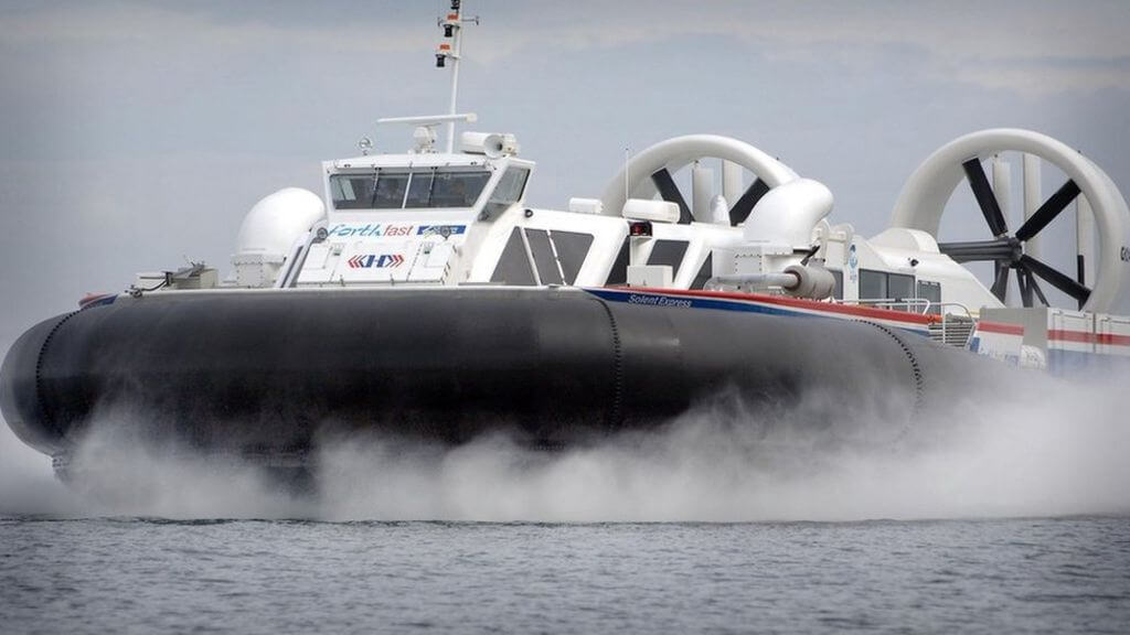
GEV and Hovercraft are Different
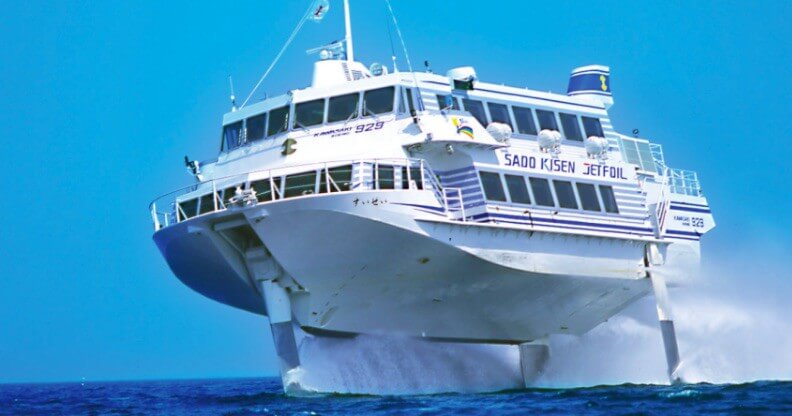
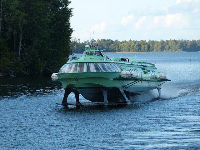
A GEV is sometimes characterized as a transition between a hovercraft and an aircraft, although this is not correct as a hovercraft is statically supported upon a cushion of pressurised air from an on-board downward-directed fan. Some GEV designs, such as the Russian Lun and Dingo, have used forced blowing under the wing by auxiliary engines to increase the high pressure area under the wing to assist the take-off; however they differ from hovercraft in still requiring forward motion to generate sufficient lift to fly. Although the GEV may look similar to the seaplane and share many technical characteristics, it is generally not designed to fly out of ground effect. It differs from the hovercraft in lacking low-speed hover capability in much the same way that a fixed-wing airplane differs from the helicopter. Unlike the hydrofoil, it does not have any contact with the surface of the water when in “flight”. The ground-effect vehicle constitutes a unique class of transportation.
Development of WIGE Crafts
The development of WIG crafts originated from observations made of the landing performance of aircraft in 1920’s. Later USA and the USSR became interested in attempting to exploit the potential benefits of ground effect. A few vehicles have been designed to explore the performance advantages of flying in ground effect, mainly over water. The operational disadvantages of flying very close to the surface have discouraged widespread applications. While USA and Germany made a few attempts, USSR was the undisputed leader up to the late 1980’s. Wing in ground effect is also a new concept of designing fast ships, which are required rescue operations, and military functions, among others. WIG craft allow to gain higher speed. The ground effect (GE) allows lift-to-drag ratio of a body to increase while cruising very close to the surface of water or ground.
WIGE Configurations
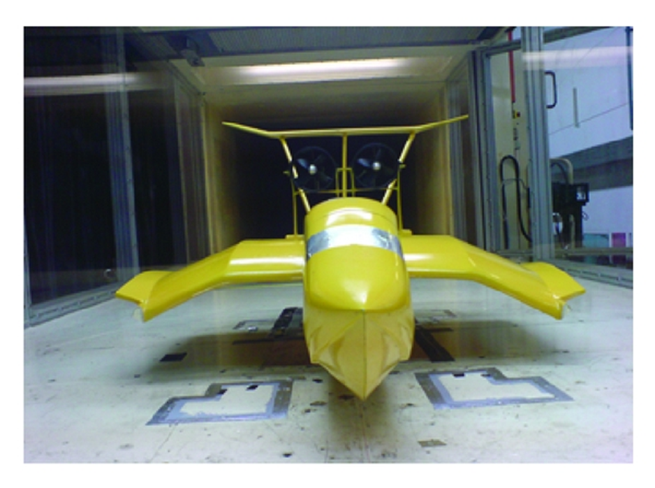
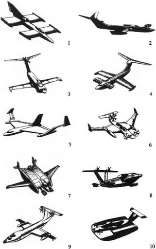
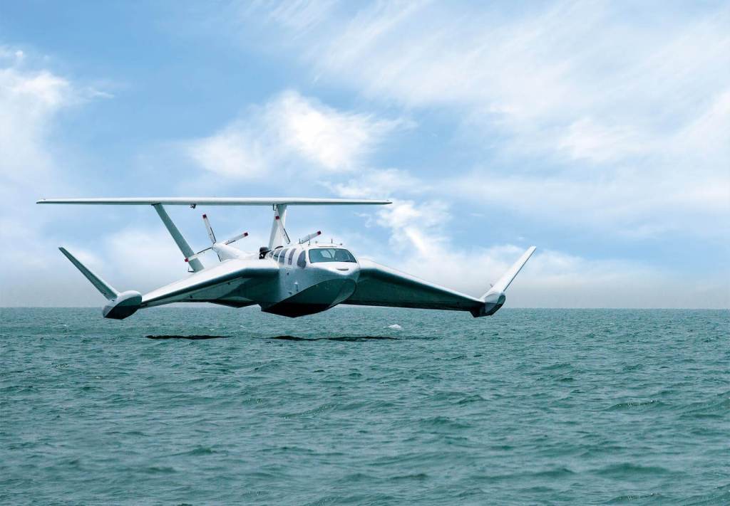
In “straight wing” Ekranoplan, the wings are significantly shorter than those of comparable aircraft, and this configuration requires a high aft-placed horizontal tail to maintain stability. The pitch and altitude stability comes from the lift slope difference between a front low wing in ground-effect (commonly the main wing) and an aft, higher-located second wing nearly out of ground-effect (generally named a stabilizer). Then there is “reverse-delta wing” allows stable flight in ground-effect through self-stabilization. The “tandem wing” has three configurations. The “biplane-style” utilises a shoulder-mounted main lift wing and belly-mounted sponsons similar to those on combat and transport helicopters. The “canard-style” is a mid-size horizontal wing near the nose of the craft directing airflow under the main lift aerofoil. This tandem design gives a major improvement during take-off, as it creates an air cushion to lift the craft above the water at a lower speed, thereby reducing water drag, which is the biggest obstacle to successful seaplane launches. “Two stubby wings” as in the tandem-aerofoil flairboat is a design that helps self-stabilizing longitudinally.
Comparison with Aircraft and Ships
Given similar hull size and power, and depending on its specific design, the lower lift-induced drag of a GEV, as compared to an aircraft of similar capacity, will improve its fuel efficiency and, up to a point, its speed. GEVs are also much faster than surface vessels of similar power, because they avoid drag from the water. Since most GEVs are designed to operate from water, accidents and engine failure typically are less hazardous than in a land-based aircraft, but the lack of altitude control leaves the pilot with fewer options for avoiding collision, and to some extent that discounts such benefits. Low altitude brings high speed craft into conflict with ships, buildings and rising land, which may not be sufficiently visible in poor conditions to avoid, and GEVs may be unable to climb over or turn sharply enough to avoid collisions. While drastic, low level manoeuvres risk contact with solid or water hazards beneath. Aircraft can climb over most obstacles, but GEVs are more limited.
In high winds, GEV must take-off into the wind, which takes the craft across successive lines of waves, causing heavy pounding, which both stresses the craft and makes passengers uncomfortable. In light winds, waves may be in any direction, which can make control difficult as each wave causes the vehicle to both pitch and roll. Their light construction makes their ability to operate in higher sea states less than that of conventional ships, but greater than the ability of hovercraft or hydrofoils, which are closer to the surface of the water. The demise of the seaplane was a result of its inability to take off or land in rough sea conditions even while flying conditions were good, and its use lasted only until runways were more commonly available.
Like conventional aircraft, greater power is needed for take-off, and, like seaplanes, ground-effect vehicles must try reduce water drag before they can accelerate to flight speed. That may require a very fine hull design. The hull has to be stable enough longitudinally to be controllable yet not so stable that it cannot lift off the water. The bottom of the vehicle must be formed to avoid excessive pressures on landing and taking off without sacrificing too much lateral stability, and it must not create too much spray, which damages the airframe and the engines. The Russian have solved this by multiple chines, a boat design with sharp change in angle in the cross section of a hull undersides and in the forward location of the jet engines. A 2014 NASA study claims that use of GEVs for passenger travel will lead to cheaper flights, increased accessibility and less pollution.
Classified As Ships
One difficulty which has delayed GEV development is the classification and legislation to be applied. The International Maritime Organization (IMO) has studied the application of rules based on the International Code of Safety for High-Speed Craft (HSC code) which was developed for fast ships such as hydrofoils, hovercraft, catamarans and the like. The Russian Rules for classification and construction of small type ‘A’ ekranoplans is a document upon which most GEV design is based. However, in 2005, the IMO classified the WIGE or GEV under the category of ships. The IMO recognizes three types of GEVs. A craft which is certified for operation only in ground effect; a craft which is certified to temporarily increase its altitude to a limited height outside the influence of ground effect but not exceeding 150 metres (490 ft) above the surface; and a craft which is certified for operation outside ground effect and exceeding 150 metres (490 ft) above the surface. These classes currently only apply to craft carrying 12 passengers or more.
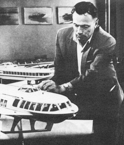
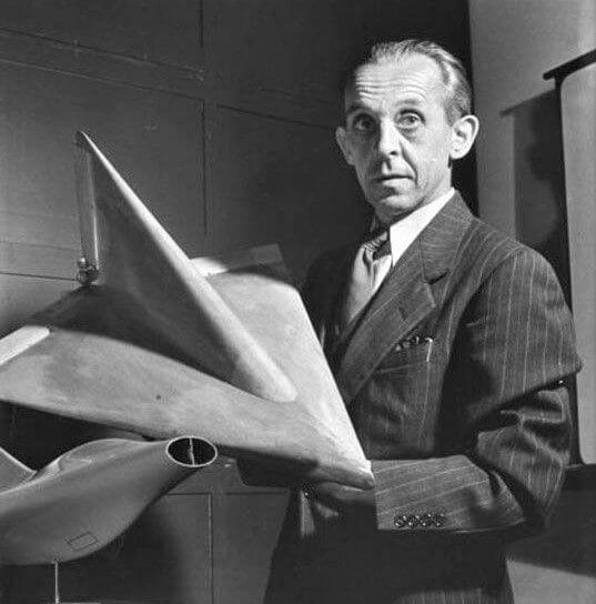
By the 1960s, the technology started maturing, in large part due to the independent contributions of Rostislav Alexeyev in the Soviet Union and German Alexander Lippisch, working in the United States. Alexeyev worked from his background as a ship designer whereas Lippisch worked as an aeronautical engineer. The influence of Alexeyev and Lippisch remains noticeable in most GEVs seen today.
Soviet Union – The Leaders
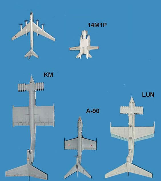
Led by Alexeyev, the Soviet Central Hydrofoil Design Bureau was the centre of ground-effect craft development in the USSR. The military potential for such a craft was soon recognized and Alexeyev received support and financial resources from Soviet leader Nikita Khrushchev. Some manned and unmanned prototypes were built, ranging up to eight tons in displacement. This led to the development of a 550-ton military ekranoplan of 92 m (302 ft) length. The craft was dubbed the Caspian Sea Monster by U.S. intelligence experts, after a huge, unknown craft was spotted on satellite reconnaissance photos of the Caspian Sea area in the 1960s. With its short wings, it looked airplane-like in plan form. Although it was designed to travel a maximum of 3 m (9.8 ft) above the sea, it was found to be most efficient at 20 m (66 ft), reaching a top speed of 300–400 knots (560–740 km/h) in research flights.

The Soviet Union produced the most successful ekranoplan so far, the 125-ton A-90 Orlyonok. These craft were originally developed as high-speed military transports and were usually based on the shores of the Caspian Sea and Black Sea. The Soviet Navy ordered 120 Orlyonok-class ekranoplans, but this figure was later reduced to fewer than 30 vessels, with planned deployment mainly in the Black Sea and Baltic Sea fleets. A few Orlyonoks served with the Soviet Navy from 1979 to 1992.

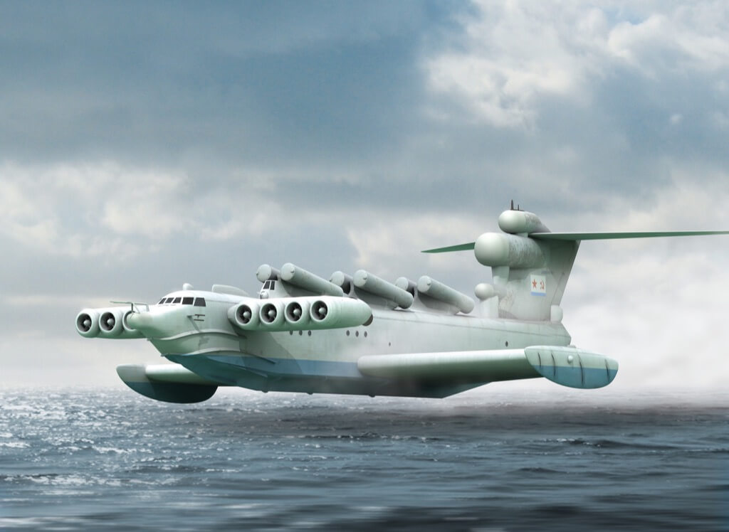
In 1987, the 400-ton Lun-class ekranoplan was built as an anti-ship missile launch platform. A second Lun, renamed Spasatel, was laid down as a rescue vessel, but was never finished. The two major problems that the Soviet ekranoplans faced were poor longitudinal stability and a need for reliable navigation.
Defence Minister Ustinov, the man who drove the projects died in 1985, and the new Minister, Marshal Sokolov, cancelled funding for the program. Only three operational Orlyonok-class ekranoplans (with revised hull design) and one Lun-class ekranoplan remained at a naval base near Kaspiysk. Since the dissolution of the Soviet Union, ekranoplans have been produced by the Volga Shipyard in Nizhniy Novgorod. Smaller ekranoplans for non-military use have been under development. The Central Hydrofoil Design Bureau (CHDB) had already developed the eight-seat Volga-2 in 1985, and Technologies and Transport is developing a smaller version called the Amphistar. The Beriev Be-2500 Neptun is a super heavy amphibious transport aircraft that, as of 2007, was in design and development by Russian design firm Beriev. The maximum takeoff weight is estimated at 2500 tons, hence its name. It was to be a “flying ship” cargo carrier, but nothing came of the project.

German WIGE
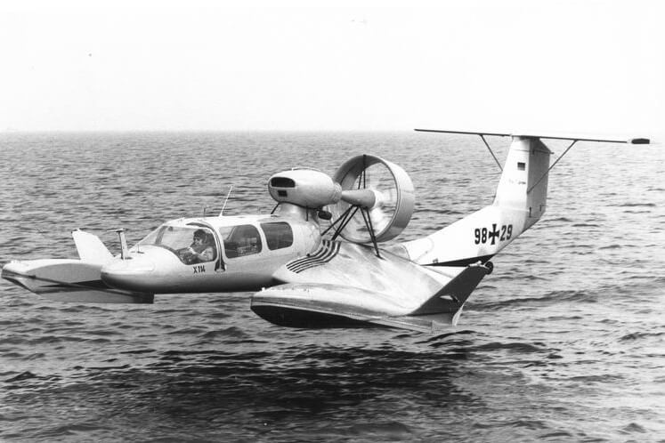
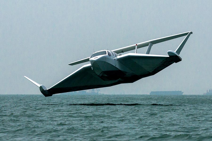
In Germany, Lippisch was asked to build a very fast boat for American businessman Arthur A. Collins. In 1963 Lippisch developed the X-112, a revolutionary design with reversed delta wing and T-tail. This design proved to be stable and efficient in ground effect and even though it was successfully tested, Collins decided to stop the project and sold the patents to a German company called Rhein Flugzeugbau (RFB), which further developed the inverse delta concept into the X-113 and the six seat X-114. These craft could be flown out of ground effect so that, for example, peninsulas could be overflown. Hanno Fischer took over the works from RFB and created his own company, Fischer Flugmechanik, which eventually completed two models. The Airfisch 3 carried two persons, and the FS-8 carried six persons. The FS-8 was to be developed by Fischer Flugmechanik for a Singapore
Australian joint venture called Flightship. Powered by a V8 Chevrolet automobile engine rated at 337 kW, the prototype made its first flight in February 2001 in the Netherlands. The company no longer exists but the prototype craft was bought by Wigetworks, a company based in Singapore and renamed as AirFish 8 at could reach a speed of 120 mph. In 2010, that vehicle was registered as a ship in the Singapore Registry of Ships. As per company website, in March 2017, Pre-Production Craft 2 officially registered as International Yacht with Langkawi International Yacht Registry (LIYR) of Malaysia and renamed as M/Y Airfish Yoyager. M/Y Airfish Voyager completed long distance endurance flight/voyage (350 nautical miles) in Straits of Malacca alongside busy international shipping lanes from Port of Malacca to the resort island of Langkawi, Malaysia, to participate in Langkawi International Maritime & Aerospace exhibition 2017 (LIMA’17). Fitted with a 7-litre V8 race-car engine, AirFish 8 is designed to be operated by two crews and classified as a merchant ship with a carrying capacity for six to eight passengers. It takes off and lands like a seaplane, and hovers just two to six metres above water at a top speed of 180 kmph.
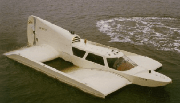
German engineer Günther Jörg, who had worked on Alexeyev’s first designs, developed a GEV with two wings in a tandem arrangement, the Jörg-II. It was the third, manned, tandem-aerofoil boat, named “Skimmerfoil”, which was developed during his consultancy period in South Africa. It was a simple and low-cost design of a first 4-seater tandem-aerofoil flairboat completely constructed of aluminium. The prototype was in the South African Air Force (SAAF) Port Elizabeth Museum till 2013 and is now in private use. During a period of more than 30 years Jörg managed to build and fly successful a series of 15 different tandem-aerofoil flairboats in different sizes and made of different materials. Bigger concepts were 25-seater, 32-seater, 60-seater, 80-seater and bigger up to the size of a passenger airplane. In 1984, Gunther W. Jörg was decorated with “Philip Morris Award” for future transportation. In 1987, the Botec Company was founded. After his death in 2010 business is continued by his daughter and former assistant Ingrid Schellhaas with her company Tandem WIG Consulting.
More Recent Developments
GEVs developed since the 1980s have been primarily smaller craft designed for the recreational and civilian ferry markets. Germany, Russia and the United States have provided most of the momentum with some development in Australia, China, Japan, Korea and Taiwan. In these countries and regions, small craft up to ten seats have been designed and built. Other larger designs as ferries and heavy transports have been proposed, but have not been carried to fruition.
Besides the development of appropriate design and structural configuration, special automatic control systems and navigation systems are also being developed. These include special altimeters with high accuracy for small altitude measurements and also lesser dependence on weather conditions. After extensive research and experimentation, it has been shown that “phase radio altimeters” are most suitable for such applications as compared to laser altimeter, isotropic or ultrasonic altimeters.
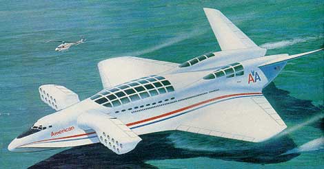
Aerocon Dash-1.6
The Aerocon Dash-1.6 wing-ship was a proposed American ground-effect vehicle intended to carry large cargos and thousands of passengers over long distances at near-aircraft speeds. The vehicle was claimed to be able to carry a combination of 1,400 tons of cargo and 2,000 passengers a distance of 11,500 miles (18,500 km) at speeds close to those of commercial airliners. The US Defense Advanced Research Projects Agency (DARPA) evaluated the Aerocon design, along with submissions from several other manufacturers, as part of a preliminary study of the concept during the 1990s to determine whether a billion-dollar program was viable, to develop a wing-ship for military uses. By the end of 1994, the Department of Defense decided that the design was too high a risk and did not offer further funding.
Other Initiatives
Universal Hovercraft developed a flying hovercraft, a prototype of which first took flight in 1996. Since 1999, the company has offered plans, parts, and kits and manufactured ground effect hovercraft called the Hoverwing. In Singapore, Wigetworks has continued development. Wigetworks has also partnered with National University of Singapore’s Engineering Department to develop higher capacity GEVs.
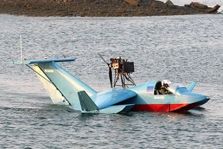
In Korea, Wing Ship Technology Corporation has developed and tested a 50-seat passenger version of a GEV named the WSH-500. Iran deployed three squadrons of Bavar 2 two-seat GEVs in September, 2010. This GEV carries one machine gun and surveillance gear, and incorporates features which reduce its radar signature in a similar manner to stealth. In October 2014, satellite images showed new images of the GEV in a shipyard in south of Iran. The GEV has two engines and no armament.
The designers Burt Rutan in 2011 and Korolev in 2015 have shown GEV projects. Estonian transport company Sea Wolf Express plans to launch passenger service in 2019 between Helsinki and Tallinn, a distance of 87 km taking only half an hour, using a Russian-built ekranoplan. The company has ordered 15 ekranoplans with maximum speed of 185 km/h and capacity of 12 passengers and they are built by Russian RDC Aqualines.
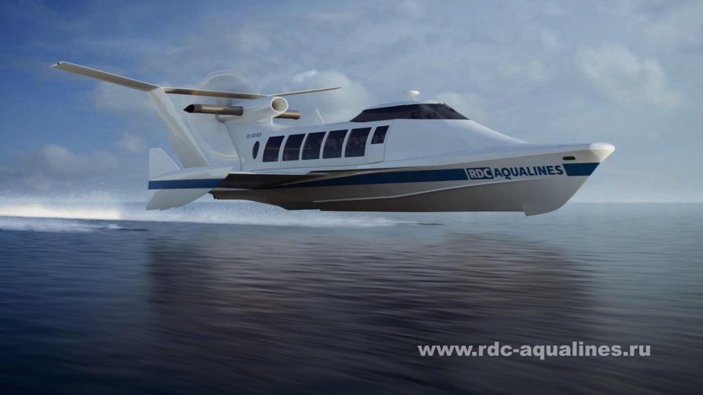
Sea Wolf Express, planned to launch passenger services on the Tallinn-Helsinki route using a Russian-built GEV. Image Source: news.err.ee
Caspian Sea Monster
The KM (Korabl Maket), literally “Ship-prototype”, known colloquially as the Caspian Sea Monster, was an experimental ground effect vehicle developed in the Soviet Union in the 1960s by the Central Hydrofoil Design Bureau (CHDB). The KM began operation in 1966, and was continuously tested by the Soviet Navy until 1980 when it crashed into the Caspian Sea. The KM was the largest and heaviest aircraft in the world from 1966 to 1988, and its surprise discovery by the United States and the subsequent attempts to determine its purpose became a distinctive event of espionage during the Cold War.
It was designed by CHDB chief designer Rostislav Alexeyev and the lead engineer V. Efimov, and manufactured at the Red Sormovo plant in Gorky (now Nizhny Novgorod). The project was notable for its massive size and payload. The KM had a wingspan of 37.6 metres (123 ft); a length of 92 m (302 ft); a maximum take-off weight of 494 tons; and was designed to fly at an altitude of 5–10 metres (16–33 ft) to use the ground effect. The KM was also undetectable to many radar systems, as it flew below the minimum altitude of detection. Considered closer to a boat, it was assigned to the Soviet Navy, but operated by test pilots of the Soviet Air Forces. The KM was documented as a marine vessel and prior to the first flight a bottle of champagne was broken against its nose, a tradition for the first voyage of a watercraft.
It served as the basis for Lun’s development. Unlike the Lun, the KM featured a constant-chord main wing and a stabilizer with notable dihedral and an unswept aft trailing edge. In June 1966, the completed KM was secretly transported along the Volga River, covered in camouflage and moving only at night, to the testing grounds on the Caspian Sea. The aircraft’s first flight was on October 16, 1966, performed by V. Loginov and Rostislav Alexeyev himself, which was very unusual as most Soviet aircraft designers never piloted their own creations. All the work was conducted under patronage of the Ministry of Shipbuilding Industry. Testing showed the KM to have an optimum (fuel efficient) cruising speed of 430 km/h (232 knots), and a maximum operational speed of 500 km/h (270 knots). The maximum speed achieved was 650 km/h (350 knots), although some sources claim up to 740 km/h (400 knots).
It was tested on the Caspian Sea for an extensive 15 years until 1980, when it was destroyed following a crash caused by pilot error. There were no human casualties, but the KM was damaged and no attempts were made to save it, it being left to float before eventually sinking a week later. The KM was deemed too heavy to recover and has remained underwater at the crash site ever since, with no plans to build a second ever made. However, the KM later became the basis for the Lun-class ekranoplan developed by the CHDB in the 1980s, which saw one example, the MD-160, enter service with the Soviet Navy and later the Russian Navy before being decommissioned in the late 1990s. The aircraft was not destroyed, but abandoned in the Caspian Sea, being visible till early 2020. After more than three decades, the aircraft was moved in 2020 to Derbent, with plans to make it the star of Derbent’s planned Patriot Park, a military museum and theme park that will display a variety of Soviet and Russian military equipment.

The KM remained the largest aircraft in the world during the entirety of its existence and is the second-largest aircraft ever built, behind the Antonov An-225 Mriya that flew for the first time in 1988, eight years after the KM’s destruction. The discovery, at the height of the Cold War, greatly concerned the CIA, which set up a dedicated task force and developed a purpose-built unmanned drone under Project AQUILINE, just to determine what the secret behind the vehicle was. In the 1980s, after the KM was already destroyed, the United States discovered it was a large ekranoplan. In the James Bond continuation novel Devil May Care published in 2008, the KM is used by the villain for smuggling. In the 007: Blood Stone video game the villain also uses an ekranoplan in an effort to escape from James Bond. , but the latter gets onboard and throws the villain off the vehicle, killing him.
Specifications of KM
The KM had 5 crew, and capacity of 50 people. It had length of 92.00 m (301 ft 10 in), wingspan of 37.60 m (123 ft 4 in), tail stabilizer span of 37 m (121 ft 5 in), and height of 21.80 m (71 ft 6 in). The empty weight: 240,000 kg (529,109 lb) and max take-off weight of 544,000 kg (1,199,315 lb). It was powered by 10 × Dobrynin VD-7 turbojet, having 127.53 kN (28,670 lbf) thrust each. The maximum speed was 500 km/h (270 knots), and cruise speed of 430 km/h (230 knots). The range was 1,500 km (810 nm). Ground effect altitude was 4–14 m (up to around 46 ft) and maximum permissible sea state was 1.2 m (3 ft 11 in).
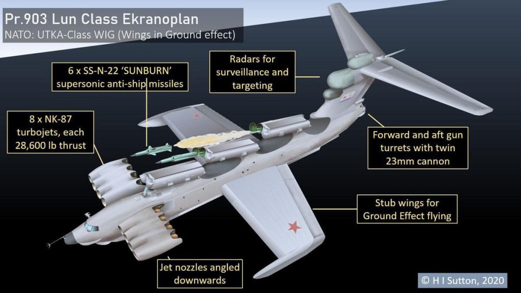
Lun-class Ekranoplan
MD-160 was the sole completed Lun-class Ekranoplan. The Lun-class ekranoplan was designed by Rostislav Evgenievich Alexeyev in 1975 and used by the Soviet and Russian navies from 1987 until sometime in the late 1990s. The name Lun comes from the Russian word for harrier. Two were planned, only one experimental was built. It was built for attack and transportation. Its empty eight was 286 tonnes. The length was 73.8 metres (242 ft), wingspan 44 metres (144 ft), height 19.2 metres (63 ft). It was propelled by 8× Kuznetsov NK-87 turbojet engines, 127.4 kN (28,600 lbf) thrust. Max speed was 297 knots (550 km/h) and max range of 1,000 nm (1,900 km). It could carry 100 ton load (220,000 pounds). Crew included six officers and nine enlisted men. Equipped for anti-surface warfare, it had the Puluchas search radar and had six fixed-elevation P-270 Moskit (Mosquito) anti-ship guided missile launchers and 4 × 23 mm PI-23 turrets (2 x 2, 2,400 rounds). The only model of Lun class ever built, the MD-160, entered service with the Black Sea Fleet in 1987.
After the Soviet nuclear submarine K-278 Komsomolets sank in 1989, a proposal emerged to have a version of Lun for use as a mobile field hospital for rapid deployment to any ocean or coastal location. It was named the Spasatel (“Rescuer”). Work was about 90% done, when the military funding ended, and it was never completed. Russia revived the idea of finishing Spasatel in 2017 with a focus on operations in the increasingly strategic Arctic region, but no work to this end appears to have happened so far. This craft was reportedly nearly complete when the project came to an indefinite halt in the 1990s, but it has sitting in Nizhny Novgorod ever since and looks to be in questionable condition today. In 2018, there were also reports that the Russian military might be interested again in fielding missile-armed ekranoplans, but there have been no clear developments in this regard since then.
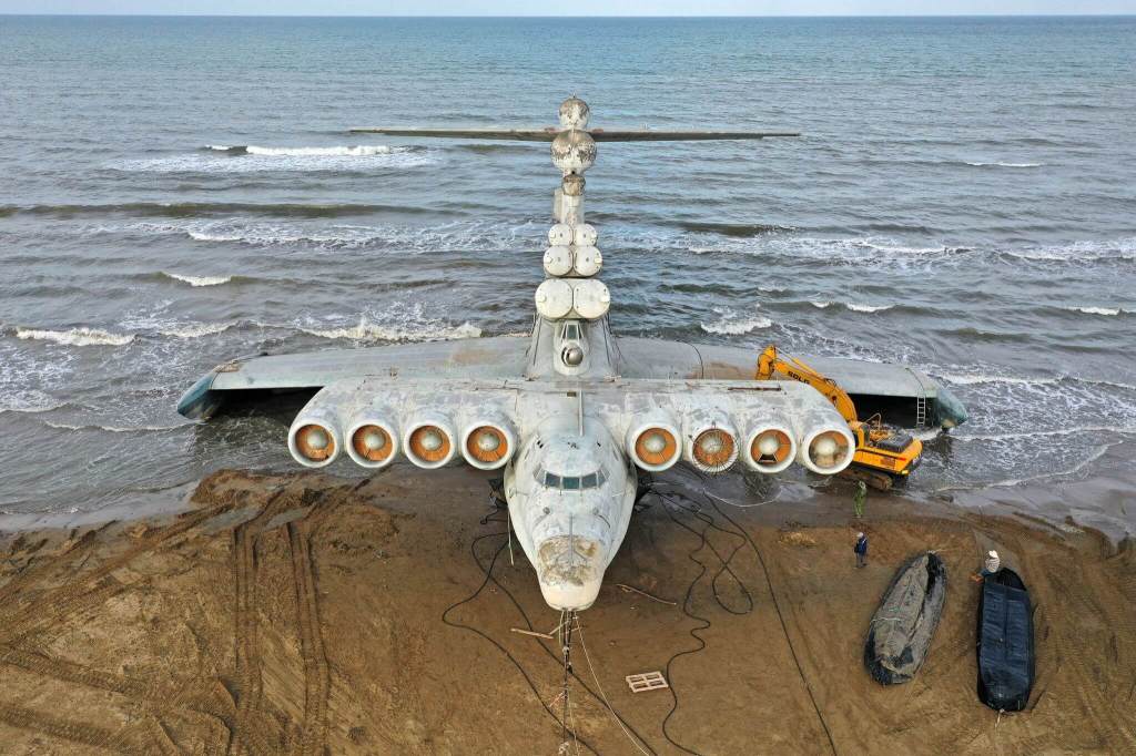
On 31 July 2020, the only completed MD-160 Lun class ekranoplan was towed from Kaspiysk naval base to Derbent, Dagestan. It will be put on display at the planned Patriot Park. The journey was approximately 100 km (62 miles) across the Caspian Sea. Moving the ekranoplan required the use of rubber pontoons, three tugboats and two escort vessels. However, while towing the vessel to its destination it was released and abandoned on the shore of the Caspian Sea just south of the town of Derbent.
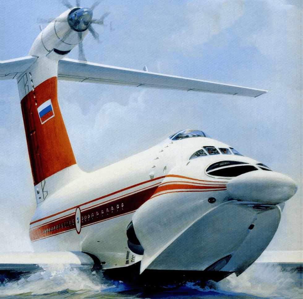
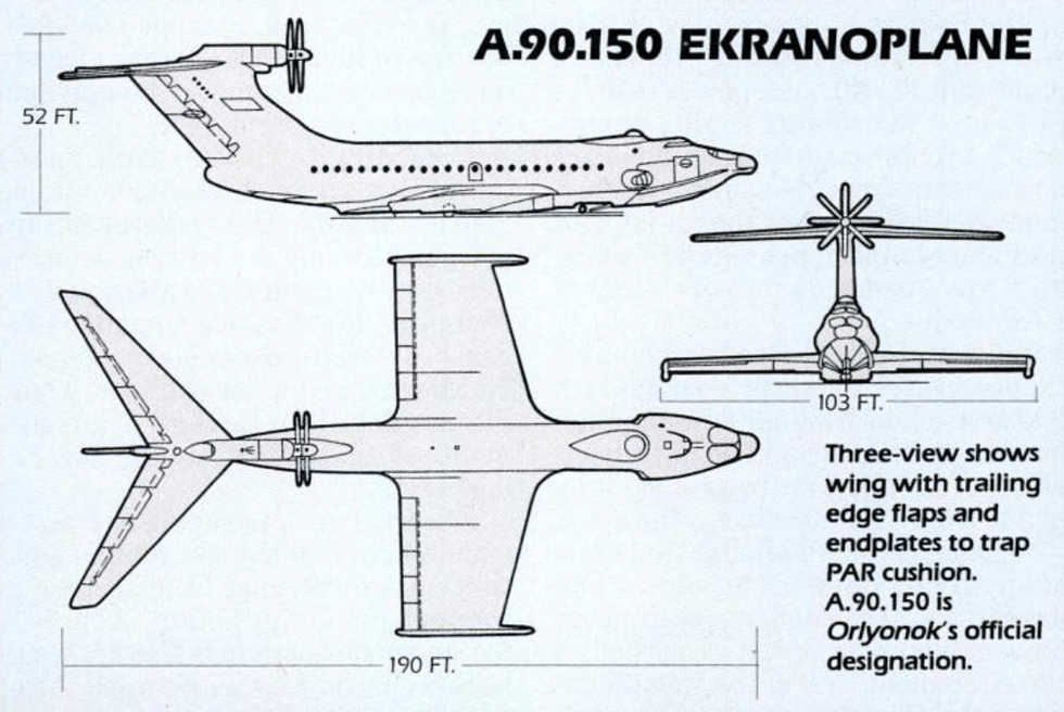
A 90 Orlyonok
The smallest of all three military Ekranoplane types built by USSR, the A-90 Orlyonok (“eaglet”) was also the only one to be operational with a small serie production. In 1971, Chief Designer R.E. Alexeyev, developed a medium-sized Ekranoplan tailored as a military transport. This project was known first through its military designation Objekt 904 “Orlan” or “Orlyonok” (little eagle or eaglet). The S-20 “Dubl” completed in 1972 according to Conways, could have been the original “Caspian monster”. The next S-23 (Caspian Sea Monster) was completed in 1975.
Sea Planes
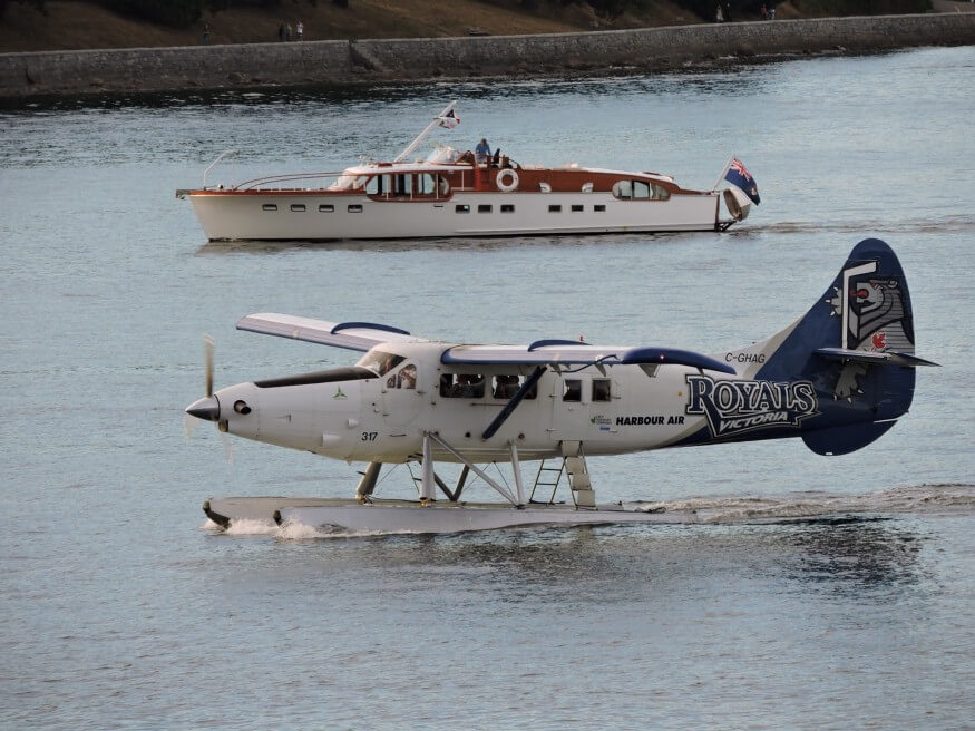
A seaplane is a powered fixed-wing aircraft capable of taking off and landing (alighting) on water. Seaplanes are usually divided into two categories based on their technological characteristics: floatplanes and flying boats; the latter are generally far larger and can carry far more. Seaplanes that can also take off and land on airfields are in a subclass called amphibious aircraft, or amphibians. Seaplanes were sometimes called hydroplanes, but currently this term applies instead to motor-powered watercraft that use the technique of hydrodynamic lift to skim the surface of water when running at speed. The use of seaplanes gradually tapered off after World War II, partially because of the investments in airports during the war. In the 21st century, seaplanes maintain a few niche uses, such as for dropping water on forest fires, air transport around archipelagos, and access to undeveloped or road-less areas, some of which have numerous lakes. Seaplanes are also used in remote areas such as the Alaskan and Canadian wilderness, especially in areas with a large number of lakes convenient for take-off and landing. They may operate on a charter basis, provide scheduled service, or be operated by residents of the area for personal use. In the Western Hemisphere, there are numerous seaplane operators in the Caribbean Sea that offer services between islands.
Personal Flight Experience – Volga 2
I went for a demonstration flight in Volga 2 Ekranoplan at Nizhniy Novgorod in Russia on two occasions in 1998/99. The aircraft has wings with short span and large chord. There were two propeller engines with large fans having vanes that directed the airflow down on the wing. Interestingly they were the same engines that powered the Russian GAZ Volga car. There was a nacelle that helped focus the airflow on to the wing under surface. The engines were on shafts extending forward so that the airflow would come down towards the lower part of the wing. Entry into the craft is like entering any boat, but inside seating is like an aircraft. The flight was over river Volga. It is an eight seater craft. The cockpit has a single Captain seat. Just behind the Captain seat are two seats with the best view. I sat on those seats in both my flights. The cockpit instruments included a direction indicator, an air speed indicator, a turn and slip indicator, and a host of engine instruments. There was no weather radar.
The engine noise level was high. Take off area was designated with buoys. For take-off the Captain opened full power. The propeller slip stream resulted in a lot of water spray came on the side windows. The acceleration was like a fast boat. The Captain pulled back the control column around 40 knots. She was airborne at 45 knots. The rest of the flight was at 60 knots. The turns were by using the rudder. They were yawing skidding turns. The here was a little bit of bank of around 3-5 degrees. Turn radius was like a medium boats’. Aim of the flight was twofold. One to see the city river side from the Volga River, and secondly a demonstration of the Ekranoplan’s capabilities. The craft was flown over stretches of the beach and also a small marshy area. The Captain then landed on a marshy patch. We then saw how he used engine power to move forward over sand and the marshy area. The engines were clearly very powerful. During cruise, after setting the power, the Captain locked the throttles for hands free operations like the Captain of a boat. Most of the flight was around a metre above the water. However he had to constantly monitor the traffic. Landing was simple throttling back which allowed the craft to slow down and gradually sit down on the water. He kept the control column back during this period. Overall it was a unique interesting experience.
Future of WIGE
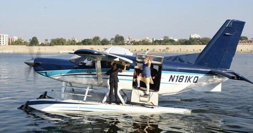
Only small WIGE are being used for the moment. There is no military employment for the present. They would be easy targets with little scope for vertical manoeuvres. Their advantage over ships is the speed, but that too can be achieved better with seaplanes. Their main potential is for tourism and joy rides. Imagine one being operated in Pangong Pso Lake in Ladakh, or in Lake Baikal in Siberia or over Amazon River. Invariably one would use a seaplane instead with much greater flexibility. Seaplanes have great role in fire-fighting and travel. These are extensively used in Scandinavian countries. They have recently been introduced in India taking Off from Ahmedabad for the Sardar Sarover Dam where Statue of Unity gets significant tourism traffic. Imagine traveling from Mumbai to Goa in a small WIGE. Since WIGE will not be able to negotiate bridges, there potential use in smaller rivers is low. They cannot be used even in cities like Venice and Amsterdam. Very few companies like the WIGETWORKS of Singapore are in the market.
Header Image Source: flowvella.com
