Introduction:
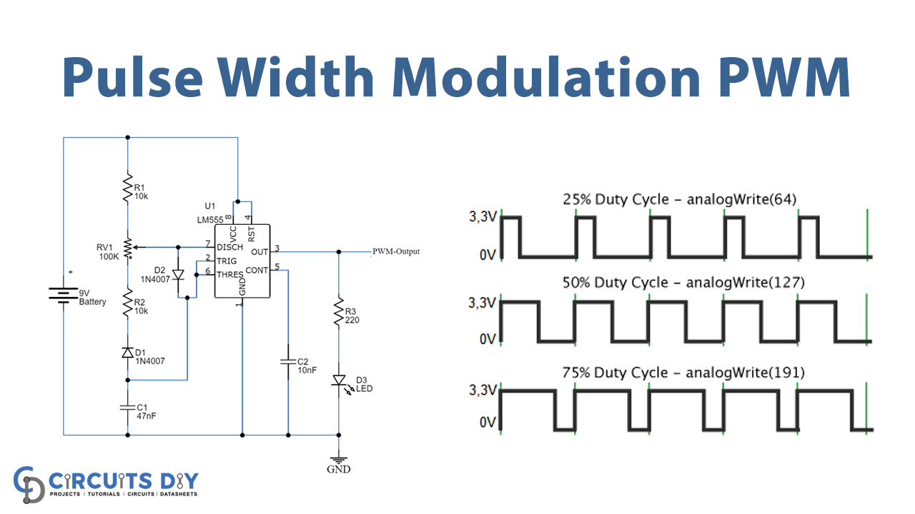
A method that is used for the reduction of the average power by splitting the input electrical power into discrete values is called Pulse-Width Modulation or Pulse-duration Modulation. The PWM is modern digital technology that by using digital signals produces analog signals. The output is a continuous square wave signal generated by the rapid changing of ON and OFF states. The behavior of the output signal is determined by its frequency and the duty cycle.
The duty cycle of PWM: It is the ratio of the time period for which the signal is in the ON state with respect to the total time of the signal to complete one cycle is called a duty cycle. A percent duty cycle indicates how much time the signal is at the HIGH state and for the rest of the time, it remains at a LOW state.
Frequency of the PWM: The frequency is the inverse of the time period. The total number of repetitions of the period per unit time is called frequency and tells the switching speed of ON and OFF states. The digital signal behaves in an analog manner by switching it ON and OFF continuously.

Hardware Components
The following components are required to make PWM Circuit
| S.no | Component | Value | Qty |
|---|---|---|---|
| 1. | IC | NE555 timer | 1 |
| 2. | Resistor | 10KΩ, 220KΩ | 2, 1 |
| 3. | Battery | 9V | 1 |
| 4. | Variable Resistor | 100KΩ | 1 |
| 5. | Capacitor | 47nF, 10nF | 1 |
| 6. | Diode | 1N4007 | 2 |
| 7. | LED | – | 1 |
NE555 Pinout

For a detailed description of pinout, dimension features, and specifications download the datasheet of 555 Timer
PWM Circuit
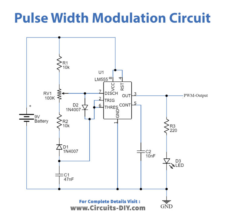
Construction & Working:
The 555 timer IC is used as the main component in this circuit, it is configured in an Astable multivibrator mode. The amplitude of the input signal varies with the width of the pulse generated at the output. At the highest value of amplitude, the maximum level of the duty cycle of pulse is attained, while at the lowest amplitude value, the duty cycle is reduced to the minimum value. The circuit outputs a continuous square pulse. The variable resistor is used to change the output frequency of the PWM controller.
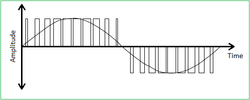
The width of the pulse is varied according to the amplitude of the input signal. Therefore, when the amplitude is maximum, the duty cycle reaches the maximum level and vice versa. The figure below shows the amplitude versus time graph.
Applications:
The PWM is a modern technology used in many applications, which include:
- Pulse width modulation is used in communication systems for the encoding of signals.
- PWM controllers are used for controlling the brightness of an LED.
- The voltage regulation is a feature of PWM which helps in controlling the speed of motors used in industries.
- Various Audio/Video amplifiers use the PWM technique.
- Electrical power can be controlled using a PWM controller.
- The analog signals can be controlled using a digital signal through a PWM technique.
Advantages:
The advantages of PWM are:
- Low cost.
- High input power and low power loss.
- Highly efficient.
- Prevent overheating of LED.