EP0244031B1 - Vorrichtung zum Lagern und Kühlen von Bier vor dem Zapfhahn - Google Patents
Vorrichtung zum Lagern und Kühlen von Bier vor dem Zapfhahn Download PDFInfo
- Publication number
- EP0244031B1 EP0244031B1 EP87200784A EP87200784A EP0244031B1 EP 0244031 B1 EP0244031 B1 EP 0244031B1 EP 87200784 A EP87200784 A EP 87200784A EP 87200784 A EP87200784 A EP 87200784A EP 0244031 B1 EP0244031 B1 EP 0244031B1
- Authority
- EP
- European Patent Office
- Prior art keywords
- cooling
- pipe
- beer
- cooling element
- storage container
- Prior art date
- Legal status (The legal status is an assumption and is not a legal conclusion. Google has not performed a legal analysis and makes no representation as to the accuracy of the status listed.)
- Expired
Links
Images
Classifications
-
- B—PERFORMING OPERATIONS; TRANSPORTING
- B67—OPENING, CLOSING OR CLEANING BOTTLES, JARS OR SIMILAR CONTAINERS; LIQUID HANDLING
- B67D—DISPENSING, DELIVERING OR TRANSFERRING LIQUIDS, NOT OTHERWISE PROVIDED FOR
- B67D1/00—Apparatus or devices for dispensing beverages on draught
- B67D1/08—Details
- B67D1/0857—Cooling arrangements
- B67D1/0858—Cooling arrangements using compression systems
- B67D1/0861—Cooling arrangements using compression systems the evaporator acting through an intermediate heat transfer means
- B67D1/0865—Cooling arrangements using compression systems the evaporator acting through an intermediate heat transfer means by circulating a cooling fluid along beverage supply lines, e.g. pythons
- B67D1/0867—Cooling arrangements using compression systems the evaporator acting through an intermediate heat transfer means by circulating a cooling fluid along beverage supply lines, e.g. pythons the cooling fluid being a liquid
-
- F—MECHANICAL ENGINEERING; LIGHTING; HEATING; WEAPONS; BLASTING
- F25—REFRIGERATION OR COOLING; COMBINED HEATING AND REFRIGERATION SYSTEMS; HEAT PUMP SYSTEMS; MANUFACTURE OR STORAGE OF ICE; LIQUEFACTION SOLIDIFICATION OF GASES
- F25D—REFRIGERATORS; COLD ROOMS; ICE-BOXES; COOLING OR FREEZING APPARATUS NOT OTHERWISE PROVIDED FOR
- F25D31/00—Other cooling or freezing apparatus
- F25D31/002—Liquid coolers, e.g. beverage cooler
-
- F—MECHANICAL ENGINEERING; LIGHTING; HEATING; WEAPONS; BLASTING
- F25—REFRIGERATION OR COOLING; COMBINED HEATING AND REFRIGERATION SYSTEMS; HEAT PUMP SYSTEMS; MANUFACTURE OR STORAGE OF ICE; LIQUEFACTION SOLIDIFICATION OF GASES
- F25D—REFRIGERATORS; COLD ROOMS; ICE-BOXES; COOLING OR FREEZING APPARATUS NOT OTHERWISE PROVIDED FOR
- F25D31/00—Other cooling or freezing apparatus
- F25D31/006—Other cooling or freezing apparatus specially adapted for cooling receptacles, e.g. tanks
Definitions
- the invention relates to a device for the storage and cooling of beer and the supply thereof to a tap via a water cooled beer pipe (python), which device further comprises at least one storage container and a cooling element arranged parallel thereto, consisting of a jacket with a cooling water inlet and an outlet, which jacket accomodates a beer pipe in the shape of a brake coil and a heat exchanger containing a pipe for passing a cooling medium e.g. freon.
- the invention also relates to a tap installation provided with such a device.
- a tap device for beer comprising at teast one tap and one storage container which are mutually connected by a water cooled beer pipe.
- the storage container is thereby arranged in a closed cooling room and is cooled by a hollow closed cooling element which is in good heat exchanging communication with the outer wall of the storage container.
- a beer pipe Located in this cooling element are a beer pipe, at least partially constructed as a so-called brake coil as well as a pipe through which a cooling medium, e.g. freon, flows. Water flows through the cooling element, cooling the contents of the storage container as a result of contact with the cooling medium pipe on the one hand and with the storage container on the other hand.
- the cooling element may have various shapes but according to a special embodiment of this known device use is made of the space which is present between two storage tanks located side by side. Said space is closed and then functions as a hollow closed cooling element in which the above-mentioned pipes are present.
- the invention is based on the fact that with smaller installations the cooling element does not have to be in direct contact with the storage container and that the storage container or the storage containers need not be arranged in a closed cooling room provided the necessary provisions for keeping the beer cool are made such as will be further described hereinafter, in particular in the characteristic part of the claims.
- An essential difference described above is furthermore that the water flowing round and thus cooling the beer coils is cooled itself by a heat exchanger located outside the room in which the beer coils are arranged.
- a cooling space is provided at the bottom side of each storage container for that purpose, water flowing through said cooling space adjoining the bottom side of the storage container.
- the wall of the storage container, as well as the bottom side of said cooling room are provided with a heat insulating layer e.g. of polyurethane foam.
- the entire cooling element is provided with a thick heat insulating layer which may also consist of polyurethane foam.
- the brake coils in the cooling element are on the one hand connected to the beer pipe in the python and on the other hand with an outlet at the bottom side of the storage container.
- a cooling circuit is present, through which water is pumped, said cooling circuit comprising at least the cooling bottom of the storage container, the inner room of the cooling element in which the brake coils are arranged and a room relatively narrowly surrounding the pipe in which the cooling medium, e.g. freon, flows.
- the cooling circuit of the python may be advantageously incorporated in the entire circuit. In that case only one cooling water pump is needed.
- a device is characterized in that the storage container and the cooling element are insulated individually, that the storage container is arranged vertically while it has a cooling space at its bottom side, which is coupled with the outlet, and that the cooling element has an inner room with the cooling water inlet at the bottom side and a cooling water outlet at the upper side coupled to the outlet via the heat exchanger surrounding the pipe.
- US-A 2 618 938 and US-A 2342 299 disclose cooling arrangements with advanced cooling devices at the circumference respectively at the inside of the beer containers in order mainly to cool the beer in the container only.
- the beer pipe which leaves the cooling element at the bottom side may thereby be advantageously provided with a rotatable coupling and a swivelling arm with which the coupling to either of the two storage containers can be effected. In this manner it will be possible to take the one container into use e.g. when the other container is being filled so that tapping is not interrupted.
- the heat exchanger preferably U-shaped, which consists of an inner pipe surrounded by a jacket, as already described above, preferably comprises elements amplifying the transfer of heat, said ,e.g. filiform elements, being fixed to the inner pipe.
- the cooling water flows along the inner pipe and the heat transferring elements and is very well cooled as a result.
- the cooling of the bottoms of the storage containers may take place e.g. by providing a cooling coil against the bottom side.
- said cooling coil is formed between two parallel plates in which a partition is present forming a spiral through-flow pipe therein.
- One of said plates may be formed by the bottom side of the storage container itself.
- a distribution pipe which is located inside the cooling element and which may be centrally connected to the storage container(s); with this construction it will be possible to provide several taps with beer from one storage container via various brake coils.
- taps are provided in the connections of the distribution pipe with the brake coils, which taps can be operated outside the cooling element.
- Said taps may also be constructed as threeway taps which makes it possible to disengage one brake coil entirely and connect it to a flushing pipe; it will be possible then to flush the entire pipe from the tap up to and including the brake coil.
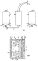
- reference numbers 1 and 2 indicate the two storage containers for the beer and number 3 indicates the cooling element located therebetween.
- Said cooling element is provided at its bottom side with a spout 4, said spout 4 being in communication with a swivelling arm 6 in which a non-return valve is provided.
- Said swivelling arm 6 may be put into communication either with tank 1 via the tap 7 or with tank 2 via the tap 8. Via said taps 7 and 8 it will also be possible to fill the tanks with beer, e.g. from a tank lorry. In the tanks there may be present, in a manner known by itself, plastic bags in which the beer is stored.
- the beer By means of pressure via the taps 9 and 10 the beer can be forced from the storage containers 1 and 2 into the brake coil or coils in the cooling element 3.
- the beer flows out of the cooling element to the python 11 which ends at the tap 12.
- Said python being cooled by water, may have a construction as illustrated in the abovemen- tioned international application WO-8 600 064.
- the storage containers 1 and 2 have a closed space 13, 14 respectively in which cooling water circulates via the inlets 15 and the outlets 16.
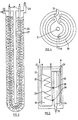
- Fig 2 diagrammatically illustrates a longitudinal section of the cooling element 3.
- Said element has an outer wall 17, e.g. of aluminium, in which the inner pipe is located.
- Arranged in the interior of said pipe 18 is the beer pipe, in the shape of a brake coil 19.
- the beer flows into the brake coil at the bottom side at 20 and is supplied to the beer pipe in the python at 21.
- the water than flows to the heat exchanger which consists of an outer jacket 24 and an inner pipe 25 through which a cooling medium, e.g. freon, flows.
- the cooling water flows out of the heat exchanger at 26.
- cooling water is led to the inlets 15 (fig 1) of the cooling bottoms of the storage containers.
- elements 27 in wire form here, amplifying the transfer of heat. Said elements are fixed to the pipe 25.
- the wall 17 is filled with insulating material, e.g. polyurethane foam.
- the supply of cooling water takes place at 22 as indicated above. Said cooling water can come directly from a pump and be led to the cooling bottoms of the storage containers at 26. Return to the pump is then effected from said cooling bottoms of the storage containers via the outlets 16 (fig 1). It is also possible, however, to send the cooling water from the pump through the cooling water jacket of the python first and from there let it follow the same route via 22 as described above. Under all circumstances, however, cooling takes place according to the reflux principle.
- Fig 3 diagrammatically illustrates, in side view, the heat exchanger of fig 2 again. From this figure it is apparent that the heat exchanger is U-shaped. The reference numerals correspond with those of fig 2.
- Fig 4 diagrammatically illustrates a special embodiment of a cooling space under a storage container.
- Said room consists of two more or less parallel plates, one of which may be the bottom of the container itself, and is divided by the partition 30 in such a manner that a spiral channel is formed from the water inlet 15 to the water outlet 16.
- 31 indicates the supply pipe which may be put into communication with the cooling element, e.g. as illustrated in fig 1.
- Fig 5 diagrammatically illustrates a cooling element suitable for supplying two taps.
- This cooling element essentially corresponds with the cooling element illustrated in fig 2.
- the reference numbers therefore correspond with the reference numbers of said fig 2.
- the inner pipe 18 Located beside the inner pipe 18 is the distribution pipe 34 to which the brake coils 32 and 33 are connected.
- Said distribution pipe may be connected to a storage container at 20 and drives the beer, via the valves 35, 36 respectively, to the brake coils 32, 33 respectively.
- Said valves can be operated outside the cooling element.
Claims (11)
Priority Applications (1)
| Application Number | Priority Date | Filing Date | Title |
|---|---|---|---|
| AT87200784T ATE48826T1 (de) | 1986-04-28 | 1987-04-25 | Vorrichtung zum lagern und kuehlen von bier vor dem zapfhahn. |
Applications Claiming Priority (2)
| Application Number | Priority Date | Filing Date | Title |
|---|---|---|---|
| NL8601082 | 1986-04-28 | ||
| NL8601082A NL8601082A (nl) | 1986-04-28 | 1986-04-28 | Inrichting voor de opslag en de koeling van bier bestemd voor het toevoeren aan een tapkraan. |
Publications (2)
| Publication Number | Publication Date |
|---|---|
| EP0244031A1 EP0244031A1 (de) | 1987-11-04 |
| EP0244031B1 true EP0244031B1 (de) | 1989-12-20 |
Family
ID=19847942
Family Applications (1)
| Application Number | Title | Priority Date | Filing Date |
|---|---|---|---|
| EP87200784A Expired EP0244031B1 (de) | 1986-04-28 | 1987-04-25 | Vorrichtung zum Lagern und Kühlen von Bier vor dem Zapfhahn |
Country Status (6)
| Country | Link |
|---|---|
| EP (1) | EP0244031B1 (de) |
| AT (1) | ATE48826T1 (de) |
| DE (1) | DE3761204D1 (de) |
| DK (1) | DK209787A (de) |
| NL (1) | NL8601082A (de) |
| NO (1) | NO871746L (de) |
Families Citing this family (8)
| Publication number | Priority date | Publication date | Assignee | Title |
|---|---|---|---|---|
| GB2289937A (en) * | 1994-06-02 | 1995-12-06 | Imi Cornelius | Chillers for supplying cold water |
| AU2182099A (en) | 1998-01-23 | 1999-08-09 | Finbar Martin Murphy | Beverage dispenser with cooling unit and python |
| EP1190984A1 (de) * | 2000-09-22 | 2002-03-27 | Imi Cornelius (Uk) Limited | Abgabegerät für gefrorene Getränke |
| EP1551751A2 (de) * | 2002-08-19 | 2005-07-13 | Icefloe Technologies Inc. | Inline-verstärker für ein getränkeabgabesystem |
| WO2007019849A2 (en) * | 2005-08-12 | 2007-02-22 | Carlsberg Breweries A/S | Beverage dispensing line cooling system and method |
| GB2436325A (en) * | 2006-03-22 | 2007-09-26 | Booth Dispensers | Beverage cooling arrangement |
| WO2010034330A1 (en) * | 2008-09-26 | 2010-04-01 | Electrolux Home Products Corporation N.V. | A beverage cooler, a refrigerator comprising such a beverage cooler and a method for cooling beverage |
| US20130340453A1 (en) * | 2012-06-22 | 2013-12-26 | SelfTAP Pro Systems Ltd. | Method and system for chilling and dispensing beverage |
Citations (2)
| Publication number | Priority date | Publication date | Assignee | Title |
|---|---|---|---|---|
| US2618938A (en) * | 1949-05-04 | 1952-11-25 | Novadel Agene Corp | Method and apparatus for beverage cooling and dispensing |
| WO1986000064A1 (en) * | 1984-06-12 | 1986-01-03 | Ummels Johannes A M | Device for tapping beer |
Family Cites Families (5)
| Publication number | Priority date | Publication date | Assignee | Title |
|---|---|---|---|---|
| US2214344A (en) * | 1935-10-24 | 1940-09-10 | John J Daly | Beverage barrel cooler |
| US2342299A (en) * | 1940-07-26 | 1944-02-22 | Novadel Agene Corp | Brew cooling and dispensing installation |
| FR1532368A (fr) * | 1967-04-27 | 1968-07-12 | Groupe de tirage de boissons gazeuses, ou non, à température constante | |
| US3809292A (en) * | 1972-01-31 | 1974-05-07 | W Branch | Stadium filler |
| GB8323126D0 (en) * | 1983-08-27 | 1983-09-28 | Soft Drink Catering Services L | Drink dispensing units |
-
1986
- 1986-04-28 NL NL8601082A patent/NL8601082A/nl not_active Application Discontinuation
-
1987
- 1987-04-24 DK DK209787A patent/DK209787A/da not_active Application Discontinuation
- 1987-04-25 DE DE8787200784T patent/DE3761204D1/de not_active Expired - Lifetime
- 1987-04-25 EP EP87200784A patent/EP0244031B1/de not_active Expired
- 1987-04-25 AT AT87200784T patent/ATE48826T1/de not_active IP Right Cessation
- 1987-04-27 NO NO871746A patent/NO871746L/no unknown
Patent Citations (2)
| Publication number | Priority date | Publication date | Assignee | Title |
|---|---|---|---|---|
| US2618938A (en) * | 1949-05-04 | 1952-11-25 | Novadel Agene Corp | Method and apparatus for beverage cooling and dispensing |
| WO1986000064A1 (en) * | 1984-06-12 | 1986-01-03 | Ummels Johannes A M | Device for tapping beer |
Also Published As
| Publication number | Publication date |
|---|---|
| DK209787D0 (da) | 1987-04-24 |
| NO871746L (no) | 1987-10-29 |
| NO871746D0 (no) | 1987-04-27 |
| DK209787A (da) | 1987-10-29 |
| NL8601082A (nl) | 1987-11-16 |
| ATE48826T1 (de) | 1990-01-15 |
| DE3761204D1 (de) | 1990-01-25 |
| EP0244031A1 (de) | 1987-11-04 |
Similar Documents
| Publication | Publication Date | Title |
|---|---|---|
| US5282561A (en) | Portable beverage dispenser | |
| US6725687B2 (en) | Drink dispensing system | |
| US4479533A (en) | Tertiary heat exchanger | |
| US5987900A (en) | Method and system for prechilling ambient waters for beverage dispensing machines and ice machines | |
| US4678104A (en) | Cold plate for beverage dispensing | |
| US3698603A (en) | Water-distributing system for a hot and cold drinking water dispenser | |
| EP0244031B1 (de) | Vorrichtung zum Lagern und Kühlen von Bier vor dem Zapfhahn | |
| WO1986000064A1 (en) | Device for tapping beer | |
| US2646667A (en) | Method of and apparatus for storing, cooling, and dispensing beverages | |
| US4617807A (en) | Involute coil cold plate | |
| WO2011047475A1 (en) | Tube-in-tube heat exchanger for beer chilling device having flexible outer shell and a plurality of inner metallic tubes | |
| US6672484B2 (en) | Integrated heat exchanger and liquid dispensing unit | |
| US7080525B2 (en) | Drink dispensing system | |
| JPS61500036A (ja) | 加圧式氷貯蔵冷水装置 | |
| US5140832A (en) | Refrigeration system for a beverage dispenser | |
| EP2238399A1 (de) | Verbesserungen bei wärmetauschern zur ausgabe von tieftemperaturbier | |
| US2682160A (en) | Method of and apparatus for storing, cooling, and dispensing beverages | |
| US20050011910A1 (en) | Drink dispensing system | |
| EP0414834B1 (de) | Vorrichtung zum speichern von wärme | |
| US4377076A (en) | Cooling arrangement, particularly for beverages | |
| MXPA01005336A (es) | Aparato de placa fria y recipiente de hielo. | |
| US2500684A (en) | Water cooler | |
| US2141221A (en) | Beer drawing and cooling system | |
| US2157744A (en) | Heat exchanger | |
| US5555734A (en) | Method for reducing sediment precipitation on heat exchangers such as water prechillers for ice machines |
Legal Events
| Date | Code | Title | Description |
|---|---|---|---|
| PUAI | Public reference made under article 153(3) epc to a published international application that has entered the european phase |
Free format text: ORIGINAL CODE: 0009012 |
|
| 17P | Request for examination filed |
Effective date: 19870428 |
|
| AK | Designated contracting states |
Kind code of ref document: A1 Designated state(s): AT BE CH DE ES FR GB IT LI LU NL SE |
|
| 17Q | First examination report despatched |
Effective date: 19881206 |
|
| GRAA | (expected) grant |
Free format text: ORIGINAL CODE: 0009210 |
|
| AK | Designated contracting states |
Kind code of ref document: B1 Designated state(s): AT BE CH DE ES FR GB IT LI LU NL SE |
|
| PG25 | Lapsed in a contracting state [announced via postgrant information from national office to epo] |
Ref country code: AT Effective date: 19891220 Ref country code: SE Effective date: 19891220 Ref country code: FR Free format text: THE PATENT HAS BEEN ANNULLED BY A DECISION OF A NATIONAL AUTHORITY Effective date: 19891220 Ref country code: CH Effective date: 19891220 Ref country code: LI Effective date: 19891220 Ref country code: IT Free format text: LAPSE BECAUSE OF FAILURE TO SUBMIT A TRANSLATION OF THE DESCRIPTION OR TO PAY THE FEE WITHIN THE PRE;WARNING: LAPSES OF ITALIAN PATENTS WITH EFFECTIVE DATE BEFORE 2007 MAY HAVE OCCURRED AT ANY TIME BEFORE 2007. THE CORRECT EFFECTIVE DATE MAY BE DIFFERENT FROM THE ONE RECORDED.SCRIBED TIME-LIMIT Effective date: 19891220 |
|
| REF | Corresponds to: |
Ref document number: 48826 Country of ref document: AT Date of ref document: 19900115 Kind code of ref document: T |
|
| REF | Corresponds to: |
Ref document number: 3761204 Country of ref document: DE Date of ref document: 19900125 |
|
| PGFP | Annual fee paid to national office [announced via postgrant information from national office to epo] |
Ref country code: BE Payment date: 19900323 Year of fee payment: 4 |
|
| PGFP | Annual fee paid to national office [announced via postgrant information from national office to epo] |
Ref country code: LU Payment date: 19900329 Year of fee payment: 4 |
|
| REG | Reference to a national code |
Ref country code: CH Ref legal event code: PL |
|
| PG25 | Lapsed in a contracting state [announced via postgrant information from national office to epo] |
Ref country code: ES Free format text: LAPSE BECAUSE OF FAILURE TO SUBMIT A TRANSLATION OF THE DESCRIPTION OR TO PAY THE FEE WITHIN THE PRESCRIBED TIME-LIMIT Effective date: 19900331 |
|
| PG25 | Lapsed in a contracting state [announced via postgrant information from national office to epo] |
Ref country code: LU Free format text: LAPSE BECAUSE OF NON-PAYMENT OF DUE FEES Effective date: 19900430 |
|
| EN | Fr: translation not filed | ||
| PLBE | No opposition filed within time limit |
Free format text: ORIGINAL CODE: 0009261 |
|
| STAA | Information on the status of an ep patent application or granted ep patent |
Free format text: STATUS: NO OPPOSITION FILED WITHIN TIME LIMIT |
|
| PG25 | Lapsed in a contracting state [announced via postgrant information from national office to epo] |
Ref country code: NL Effective date: 19901101 |
|
| 26N | No opposition filed | ||
| NLV4 | Nl: lapsed or anulled due to non-payment of the annual fee | ||
| PG25 | Lapsed in a contracting state [announced via postgrant information from national office to epo] |
Ref country code: DE Effective date: 19910101 |
|
| PG25 | Lapsed in a contracting state [announced via postgrant information from national office to epo] |
Ref country code: GB Effective date: 19910425 |
|
| PG25 | Lapsed in a contracting state [announced via postgrant information from national office to epo] |
Ref country code: BE Effective date: 19910430 |
|
| BERE | Be: lapsed |
Owner name: UMMELS JOHANNES ANTOINETTA MICHAEL Effective date: 19910430 |
|
| GBPC | Gb: european patent ceased through non-payment of renewal fee |