US856140A - Triple-pipe beer-cooler. - Google Patents
Triple-pipe beer-cooler. Download PDFInfo
- Publication number
- US856140A US856140A US30188706A US1906301887A US856140A US 856140 A US856140 A US 856140A US 30188706 A US30188706 A US 30188706A US 1906301887 A US1906301887 A US 1906301887A US 856140 A US856140 A US 856140A
- Authority
- US
- United States
- Prior art keywords
- pipes
- pipe
- beer
- secured
- heads
- Prior art date
- Legal status (The legal status is an assumption and is not a legal conclusion. Google has not performed a legal analysis and makes no representation as to the accuracy of the status listed.)
- Expired - Lifetime
Links
Images


Classifications
-
- F—MECHANICAL ENGINEERING; LIGHTING; HEATING; WEAPONS; BLASTING
- F28—HEAT EXCHANGE IN GENERAL
- F28D—HEAT-EXCHANGE APPARATUS, NOT PROVIDED FOR IN ANOTHER SUBCLASS, IN WHICH THE HEAT-EXCHANGE MEDIA DO NOT COME INTO DIRECT CONTACT
- F28D7/00—Heat-exchange apparatus having stationary tubular conduit assemblies for both heat-exchange media, the media being in contact with different sides of a conduit wall
- F28D7/10—Heat-exchange apparatus having stationary tubular conduit assemblies for both heat-exchange media, the media being in contact with different sides of a conduit wall the conduits being arranged one within the other, e.g. concentrically
- F28D7/103—Heat-exchange apparatus having stationary tubular conduit assemblies for both heat-exchange media, the media being in contact with different sides of a conduit wall the conduits being arranged one within the other, e.g. concentrically consisting of more than two coaxial conduits or modules of more than two coaxial conduits
Definitions
- This invention relates to triple pipe beer coolers adapted to permit a continuous circulation in separate pipes, respectively, of beer, brine and ammonia, the various pipes being arranged and connected at their ends to form a continuous coil, having an inlet at one end and an outlet at the other.
- the invention relates more particularly to an improvement in :he construction of the heads or bends connecting in alternate relation the opposite ends of the pipes of the coil.
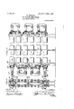
- Figure 1 is a side elevation of myimproved triple pipe beer cooler
- Fig. 2 is an end elevation
- Fig. 3 is a vertical section on an enlarged scale of one of the heads
- Fig. 4 is a section upon the line 4 4 of Fig. 3
- Fig. 5 is avertical section on an enlarged scale through a single pipe-unit and head at the inlet or outlet end of the apparatus
- Fig. 6 is a horizontal section of the same.
- the numerals 1 indicate a series of pipe-units arranged in parallel relation one above the other and supported at their'ends in a manner to be described later on, and at a central portion by moansof a frame 2.
- Each of the pipe-units 1 comprises aninner pipe 3 for ammonia, an intermediate pipe 4, for beer, and an outer pipe 5, for brine.
- These pipes are concentrically arranged in spaced relat-ion, and, as will be seen, the beer will circulate in the space 6 between the pi es 3 and 4 and will thus travel in a thin s eet, as it were, between the ammonia and the brine.
- each unit is connected at 0pposite ends with the corresponding pipes of adjacent units in a manner to aiiord a continuous circulation of the di'erent liquids employed throughout the entire series of pipes, and as all of these connections are the same, the description of one will suffice.
- low head or casting having two parallel walls, namely, a rear wall 8 and a front wall 9,. affording between them a chamber 10.
- the rear wall 8 is provided, toward its outer ends, with two screw-threadedy apertures into the outer ends of the pipes made perfectly tight through the medium of solder 11.
- the pipes 5 are about five inches in diameter, in actual practice, and are intended for the circulation of brine.
- the intermediate pipes 4 of the two units, connected by the head 7, are shown to project beyond the outer ends of the pipes 5, and their outer ends are rolled and expanded, as indicated at 12, to be firmly secured in apertures formed in the front wall 9 of thehead 7.
- These pipes 4 are of j copper and areintended for circulation of beer.
- each of t ese sections has at its outer edge three or more apertured lugs 17 by means of which they are secured to the front of the headr 7.
- the two sections 15 and 16 are divided vertically with respect to the position of the apparatusshown and at their meeting edges have a tongue and groove connection 21, which connection will be further re-inforced by packing, as will be understood.
- the outer wall 9 of the head 7 is provided with a continuous groove 22 into which is inserted metal or other packing 23, and each of the sections of the cap 13 is provided on its inner side with a ⁇ tongue 24 which'is adapted to seat in the groove 22 and to be irmly pressed against the packing 23 by screwing up the nuts 20.
- Each4 of the sections 15 and 16 is provided with semicircular recesses 25 which, when said sections This is accom? lugs 1.7 and op-v TOO are placed together, form apertures 26 through which the innermost pipes 3 project.
- Each ol ⁇ v said sections l5 and 16 is also provided on its outer side, above and below each of the semi-circular recesses therein, with lugs 27 which are adapted to aline.
- Bolts 28 are passed through these alining apertures and have nuts 29 applied to their ends for securing the two halves of the cap together.
- the pipes 3, as above stated, extend through the sectional cap 13, which cap is provided in its outer face with recessed seats 30 surrounding the apertures 26 and into which seats are inserted annular packing rings 31 which closely embrace the pipes 3 and are firmly compressed into position by means of split sleeves 32 affording an annular llance 33 which enters the seat 30 and cngages the packing 31.
- Each of the sections of the sleeve 32 is provided with a projecting ⁇ lug 34 in each of which is formed a semi-circular recess 35 and a bolt-hole 36.
- the outer ends of the pipes 3 are united by means of a rcturn-bcnd4() which permits circulation of thc ammonia from one pipe 3 to the next adjacent pipe and this connection is made as follows:
- the outer en'd portion of each of the pipes 3 is screw-threaded and on these screw-threaded portions are screwed collars 41, the joint being made gas-tight at the rear sides of the cellars by means of solder 42.
- the outer ends of the ipes 3 and the corresponding outer end portion of the collars 41 are recessed to provideannular seats 43 into which seats are inserted metal packing 44.
- the opening therein is surrounded by an annular iange 45, which flanges are adapted to be inserted in the seat 43 in contact with the metal packing 44.
- the return-bend 40 is provided on opposite sides and near each end with apertured lugs, 46, through the apertures in which are passed screw-threaded ends of bolts 47 having hooked ends 48 engaging the rear sides of the respective collars 41.
- connection between the pipes 3 and the returnbend 4 comprising the collars 41, irmly secured on the ends of said pipes, is a very secure one and this is an important consideration as the pipes 3 are for the circulation ol' ammonia, and it is necessary to prevent the possibility of the escape of ammonia around the screw-threads of the pipes, which is accomplished by the solder 42, and at the connections between said pi es and the returnbend, which is accomp is ied by the packing 44 and the manner of firmly drawing the flanges of the return-bend into contact with the said packing and the outer ends ol' the pipes 3.
- the Vcap 13 and the sleeves 32 are made in sections. By removing the nuts from the bolts, by means of which these parts are connected tothe head 7 and to cach other, the sections of the cap 13 and sleeves 32 may be removed from about the pipes 3, and in a similar man-ner the return-bends 4 may be withdrawn fromA the ends of said pipes in order that they may be readilyA drawn through the pi e 4.
- ach of the heads 7 is provided on its front face,at each corner, with apertured lugs 49 so thatwhen said heads are placed one upon the other they may be unlted by means of bolts 5() passed through said apertures andhaving nuts 51 IOO applied thereto,l th-e heads, when so united,
- the lowermost head 7 at one end ofthev apparatus-and the head 53 at the other have secured yto them standards or bases 52 which rest upon the floor and support the apparatus as a whole in connection with frame 2.
- the heads 53 at the respective ends of the coil' are the same in construction as those just described, eX- cept that it is only necessary that ⁇ they should provide for a single pipe-unit instead of for two pipe-units.
- the pipe 3 oi the lowermost unit 1 is suitably connected to a suction-pipe or ammonia outlet 54 whilethe head 53 of said unit is provided with a brineoutlet pipe 55 and the cap 13 with a beer inlet 56.
- the upper unit 1 has'a pipe 3 connected with an ammonia supply pipe 57 while its cap 13 is provided with a beer outlet 58 and its head 53 with a brine inlet 5S).
- a beer coolingv apparatus in combination with a series of pipe-units each of which comprises a plurality of pipes concentrically arranged one within the other in spaced relation, a series of hollow heads, each of said heads having the ends of two adjacent outermost ipes secured in Vits near walliand the ends ofp two adjacent intermediate pipes secured in its far wall, sectional caps secured to each of. said heads and aiording communication between the intermediate pipes thereof, the innermost pipes of two adjacent units continuing through and being supported by said caps, collars secured on the outer ends of the' innermost pipes and of a diameter less than said intermediate pipes, and return-bends connecting the ends of adjacent innermost pipes and-coperating with said collars to form gas-tight joints.
- Y 2 In a beer cooling apparatus, in combination with .a series of pipe-units each of which comprises a plurality of pipes concentrically arranged one within the other in spaced relation, a series of hollow heads, each of said heads having the ends of two adjacent outermost ipes secured in its near wall and the ends o?
- a beer cooling apparatus in combination with a series of pipe-units each of which comprises a pluralityof pipes concentwo innermost pipesle continuing theret rough and affording annular seats sur-l rounding said pipes, split s each of said innermost justable connection wit said caps and vprovided with annular tongues engaging in said seats, collars secured on the ends of said ineeves surrounding nermost pipes, each of said collars being of a diameter to pass through said intermediate pipes, and return-bends removably secured to the ends of adjacent innermost ipes and cooperating with said collars to liorm gastight joints.
- a series of pipe-units each of' which comprises a plurality of pipes concentrically arranged one within j the other in spaced relation, a series of hollow heads each ipes and having adpipes, keach of'said caps of said heads having the ends of the outermost pipes of two adjacent units secured in its near wall and the intermediate pipes of such units secured in its far wall, said head having a grooved seat provided on its outer face, sectional caps secured to said heads and having tongues engaging in said seats, means for connecting the meetmg edges of each cap together involving a tongue and groove joint, each ofsaid affording communication between adjacent intermediate pipes and having the' innermost pipes of through, split sleeves surrounding said innermost pipes and secured to said caps, and return-bends removably secured to the outer ends of adj acent innermost pipes.
Description
No. 856,140. PATENTED JUNE 4, 1907.
W. GRIESSER. A
TRIPLE PIPE BEER COOLER. APPLIUATION FILED 21:13.19, 1906.
afg?.
PATENTED JUNE 4, 1907.
W. GRIESSER. TRIPLE PIPE BEER COOLER.
APPLIGATION FILED FEB. 19. 1906.
3 SHEETS-SHEET 2.
AZa '745i 661966 .FB/gm No. 856,140. PATENTED JUNE 4, 1907.
W. GRIEssER. l
' TRIPLE PIPE BEER COOLER.
APPLICATION FILED PEB. 19, 1906.
3 SHEETS-SHEET 3:
A jvvz for' r/Z/Ve AZ772 @wieda er WILHELM GRIESSER, OFIJOPLIN, MISSOURI, ASSIGNOR TO OLGA KOEHN,
DOING BUSINESS UNDER THE NAME OF BREWERY EQUIPMENT PLY` CO., OF NEW YORK, N. Y.
& SUP- TREFLSEPIPE BEERCOOL-ER.
To all whom, it may concern:
Be it known that I, WILHELM GRIEssER, a citizen of the United States, residing at Joplin, in the county of Jasper and State of Missouri, have invented new and useful Improvements in Triple-Pipe Beer-Coolers, of which the following is a specification.
This invention relates to triple pipe beer coolers adapted to permit a continuous circulation in separate pipes, respectively, of beer, brine and ammonia, the various pipes being arranged and connected at their ends to form a continuous coil, having an inlet at one end and an outlet at the other.
The invention relates more particularly to an improvement in :he construction of the heads or bends connecting in alternate relation the opposite ends of the pipes of the coil.
In order that the said invention may be clearly understood I have illustrated `vthe same in the accompanying drawings, in which:
Figure 1 is a side elevation of myimproved triple pipe beer cooler; Fig. 2 is an end elevation; Fig. 3 is a vertical section on an enlarged scale of one of the heads; Fig. 4 is a section upon the line 4 4 of Fig. 3; Fig. 5 is avertical section on an enlarged scale through a single pipe-unit and head at the inlet or outlet end of the apparatus; and Fig. 6 is a horizontal section of the same.
Referring now to these drawings, the numerals 1 indicate a series of pipe-units arranged in parallel relation one above the other and supported at their'ends in a manner to be described later on, and at a central portion by moansof a frame 2. Each of the pipe-units 1 comprises aninner pipe 3 for ammonia, an intermediate pipe 4, for beer, and an outer pipe 5, for brine. These pipes are concentrically arranged in spaced relat-ion, and, as will be seen, the beer will circulate in the space 6 between the pi es 3 and 4 and will thus travel in a thin s eet, as it were, between the ammonia and the brine. The pipes of each unit are connected at 0pposite ends with the corresponding pipes of adjacent units in a manner to aiiord a continuous circulation of the di'erent liquids employed throughout the entire series of pipes, and as all of these connections are the same, the description of one will suffice.
Referring now to Fig. 3, 7. indicates a hol- Specifcaton of Letters Patent. Application led February 19, 1906, Serial No. 301,887.
vwhich are screwed '5 of two adjacent units. These joints are Patented J une 4, 1 907.
low head or casting having two parallel walls, namely, a rear wall 8 and a front wall 9,. affording between them a chamber 10. The rear wall 8 is provided, toward its outer ends, with two screw-threadedy apertures into the outer ends of the pipes made perfectly tight through the medium of solder 11. The pipes 5 are about five inches in diameter, in actual practice, and are intended for the circulation of brine. yThe intermediate pipes 4 of the two units, connected by the head 7, are shown to project beyond the outer ends of the pipes 5, and their outer ends are rolled and expanded, as indicated at 12, to be firmly secured in apertures formed in the front wall 9 of thehead 7. These pipes 4 are of j copper and areintended for circulation of beer. 13 indicates a sectional cap which is applied to the front face of the head 7, the sections being recessed on their inner sides to form, when applied to the head 7, a chamber 14 to provide for the circulation of the beer from one pipe 4 to the next adjacent pipe 4. The two sections of the cap 13 are indicated, respectivel by the numerals 15 and 16 and each of t ese sections has at its outer edge three or more apertured lugs 17 by means of which they are secured to the front of the headr 7. plished through the medium of bolts 18 which have a central plain portion adapted to seat in the apertures of the posite screw-threaded ends, one of which is screwed into screw-threaded apertures of projections 19 on the front of the head 7 and the other of which receives nuts- 20 which bear against 'the lugs17. The two sections 15 and 16 are divided vertically with respect to the position of the apparatusshown and at their meeting edges have a tongue and groove connection 21, which connection will be further re-inforced by packing, as will be understood. The outer wall 9 of the head 7 is provided with a continuous groove 22 into which is inserted metal or other packing 23, and each of the sections of the cap 13 is provided on its inner side with a` tongue 24 which'is adapted to seat in the groove 22 and to be irmly pressed against the packing 23 by screwing up the nuts 20. Each4 of the sections 15 and 16 is provided with semicircular recesses 25 which, when said sections This is accom? lugs 1.7 and op-v TOO are placed together, form apertures 26 through which the innermost pipes 3 project. Each ol`v said sections l5 and 16 is also provided on its outer side, above and below each of the semi-circular recesses therein, with lugs 27 which are adapted to aline. Bolts 28 are passed through these alining apertures and have nuts 29 applied to their ends for securing the two halves of the cap together. The pipes 3, as above stated, extend through the sectional cap 13, which cap is provided in its outer face with recessed seats 30 surrounding the apertures 26 and into which seats are inserted annular packing rings 31 which closely embrace the pipes 3 and are firmly compressed into position by means of split sleeves 32 affording an annular llance 33 which enters the seat 30 and cngages the packing 31. Each of the sections of the sleeve 32 is provided with a projecting` lug 34 in each of which is formed a semi-circular recess 35 and a bolt-hole 36. When thc two sections of thesleevcs 32 are laced together about the pipes 3 the semi-circular recesses 35 form apertures for bolts 36a, which have plain portions seating in such apertures and opposite screw-threaded ends, one of which is screwed into screw-threaded apertures formed in lugs 37 provided on the front face of the cap 13, and the other of which receives nuts 3S by means of which the t sleeve may bc drawn into iirin contact with ythe packing 31 in the seat 30. Bolts 39, in-
serted through the bolt-holes 36 of the lugs 34, secure the two sections ofthe sleeve 32 together and firmly clamp thcmabout the pipes 3. i
The outer ends of the pipes 3 are united by means of a rcturn-bcnd4() which permits circulation of thc ammonia from one pipe 3 to the next adjacent pipe and this connection is made as follows: The outer en'd portion of each of the pipes 3 is screw-threaded and on these screw-threaded portions are screwed collars 41, the joint being made gas-tight at the rear sides of the cellars by means of solder 42. The outer ends of the ipes 3 and the corresponding outer end portion of the collars 41 are recessed to provideannular seats 43 into which seats are inserted metal packing 44. At oppogite ends of the return-bend the opening therein is surrounded by an annular iange 45, which flanges are adapted to be inserted in the seat 43 in contact with the metal packing 44. The return-bend 40 is provided on opposite sides and near each end with apertured lugs, 46, through the apertures in which are passed screw-threaded ends of bolts 47 having hooked ends 48 engaging the rear sides of the respective collars 41. By means of nuts 43L applied to the screw-threaded ends of the bolts 47 the return-bend 40 is drawn into firm contact with t he ends of the pipes 3 and with the packing 44 surrounding said pipes. The connection between the pipes 3 and the returnbend 4 comprising the collars 41, irmly secured on the ends of said pipes, is a very secure one and this is an important consideration as the pipes 3 are for the circulation ol' ammonia, and it is necessary to prevent the possibility of the escape of ammonia around the screw-threads of the pipes, which is accomplished by the solder 42, and at the connections between said pi es and the returnbend, which is accomp is ied by the packing 44 and the manner of firmly drawing the flanges of the return-bend into contact with the said packing and the outer ends ol' the pipes 3. Owing to the firm and gas-tight connect-ion of the collarsy 41 with the iipes 3 it is not desirable to remove these co lars at any time, and hence the construction described has in view to permit the pipes to be removed from the apparatus without it besin ing necessary to remove the collars 41. l? or this purpose the Vcap 13 and the sleeves 32 are made in sections. By removing the nuts from the bolts, by means of which these parts are connected tothe head 7 and to cach other, the sections of the cap 13 and sleeves 32 may be removed from about the pipes 3, and in a similar man-ner the return-bends 4 may be withdrawn fromA the ends of said pipes in order that they may be readilyA drawn through the pi e 4. to'permit`the -latter to be cleaned. ach of the heads 7 is provided on its front face,at each corner, with apertured lugs 49 so thatwhen said heads are placed one upon the other they may be unlted by means of bolts 5() passed through said apertures andhaving nuts 51 IOO applied thereto,l th-e heads, when so united,
forming a stand or sup ort for'readily holding the pipe-units of t 1e apparatus in position at their outer e'nds. The lowermost head 7 at one end ofthev apparatus-and the head 53 at the other have secured yto them standards or bases 52 which rest upon the floor and support the apparatus as a whole in connection with frame 2. The heads 53 at the respective ends of the coil' are the same in construction as those just described, eX- cept that it is only necessary that `they should provide for a single pipe-unit instead of for two pipe-units. The pipe 3 oi the lowermost unit 1 is suitably connected to a suction-pipe or ammonia outlet 54 whilethe head 53 of said unit is provided with a brineoutlet pipe 55 and the cap 13 with a beer inlet 56. The upper unit 1 has'a pipe 3 connected with an ammonia supply pipe 57 while its cap 13 is provided with a beer outlet 58 and its head 53 with a brine inlet 5S).
While I have described a cooling apparatus intended more particularly for use in cooling beer, it will be apparent nevertheless that a series of pipes connected up as described can be utilized for heating purposes as well as for cooling for instance, steam could be IIS collars and screw-threaded ends passed through theintermediate pipesfor the purpose ol heating the water passing through the inner and outer pipes.
Having thus fully described my invention, y
what I c im as new and desire to secure by Letters Patent, is:
1. In a beer coolingv apparatus, in combination with a series of pipe-units each of which comprises a plurality of pipes concentrically arranged one within the other in spaced relation, a series of hollow heads, each of said heads having the ends of two adjacent outermost ipes secured in Vits near walliand the ends ofp two adjacent intermediate pipes secured in its far wall, sectional caps secured to each of. said heads and aiording communication between the intermediate pipes thereof, the innermost pipes of two adjacent units continuing through and being supported by said caps, collars secured on the outer ends of the' innermost pipes and of a diameter less than said intermediate pipes, and return-bends connecting the ends of adjacent innermost pipes and-coperating with said collars to form gas-tight joints.
` 3. In a beer cooling apparatus, in combination with a series of pipe-units each of which comprises a pluralityof pipes concentwo innermost pipesle continuing theret rough and affording annular seats sur-l rounding said pipes, split s each of said innermost justable connection wit said caps and vprovided with annular tongues engaging in said seats, collars secured on the ends of said ineeves surrounding nermost pipes, each of said collars being of a diameter to pass through said intermediate pipes, and return-bends removably secured to the ends of adjacent innermost ipes and cooperating with said collars to liorm gastight joints.
4. Ina beer cooling apparatus, in combination with a series of pipe-units each of' which comprises a plurality of pipes concentrically arranged one within j the other in spaced relation, a series of hollow heads each ipes and having adpipes, keach of'said caps of said heads having the ends of the outermost pipes of two adjacent units secured in its near wall and the intermediate pipes of such units secured in its far wall, said head having a grooved seat provided on its outer face, sectional caps secured to said heads and having tongues engaging in said seats, means for connecting the meetmg edges of each cap together involving a tongue and groove joint, each ofsaid affording communication between adjacent intermediate pipes and having the' innermost pipes of through, split sleeves surrounding said innermost pipes and secured to said caps, and return-bends removably secured to the outer ends of adj acent innermost pipes.
In .testimony whereof I have hereunto set my hand in presence of two subscribing witnesses.
WILHELM GRIESSER. Witnesses:
HENRY J. RoBEsoN, CHAs.W. Gnmssnn.
caps providing a chamber adjacent units continuing thereu
Priority Applications (1)
| Application Number | Priority Date | Filing Date | Title |
|---|---|---|---|
| US30188706A US856140A (en) | 1906-02-19 | 1906-02-19 | Triple-pipe beer-cooler. |
Applications Claiming Priority (1)
| Application Number | Priority Date | Filing Date | Title |
|---|---|---|---|
| US30188706A US856140A (en) | 1906-02-19 | 1906-02-19 | Triple-pipe beer-cooler. |
Publications (1)
| Publication Number | Publication Date |
|---|---|
| US856140A true US856140A (en) | 1907-06-04 |
Family
ID=2924596
Family Applications (1)
| Application Number | Title | Priority Date | Filing Date |
|---|---|---|---|
| US30188706A Expired - Lifetime US856140A (en) | 1906-02-19 | 1906-02-19 | Triple-pipe beer-cooler. |
Country Status (1)
| Country | Link |
|---|---|
| US (1) | US856140A (en) |
Cited By (3)
| Publication number | Priority date | Publication date | Assignee | Title |
|---|---|---|---|---|
| US2597744A (en) * | 1948-07-20 | 1952-05-20 | Sunroc Refrigeration Company | Tube-in-tube heat transfer unit |
| US3093397A (en) * | 1960-02-15 | 1963-06-11 | Fmc Corp | Flange connector |
| US3386497A (en) * | 1966-09-26 | 1968-06-04 | Robert H. Feldmeier | Regenerative heat exchanger for heavy liquids |
-
1906
- 1906-02-19 US US30188706A patent/US856140A/en not_active Expired - Lifetime
Cited By (3)
| Publication number | Priority date | Publication date | Assignee | Title |
|---|---|---|---|---|
| US2597744A (en) * | 1948-07-20 | 1952-05-20 | Sunroc Refrigeration Company | Tube-in-tube heat transfer unit |
| US3093397A (en) * | 1960-02-15 | 1963-06-11 | Fmc Corp | Flange connector |
| US3386497A (en) * | 1966-09-26 | 1968-06-04 | Robert H. Feldmeier | Regenerative heat exchanger for heavy liquids |
Similar Documents
| Publication | Publication Date | Title |
|---|---|---|
| US2151540A (en) | Heat exchanger and method of making same | |
| US2160898A (en) | Heat exchange apparatus for rectifying columns | |
| US856140A (en) | Triple-pipe beer-cooler. | |
| JP6515581B2 (en) | Separation membrane module | |
| US1777356A (en) | Heat-interchange apparatus | |
| US872175A (en) | Cooling apparatus. | |
| US2099493A (en) | Double pipe heat exchanger | |
| US2211514A (en) | Heat exchanger | |
| US2125972A (en) | Heat exchanger | |
| US1884080A (en) | Heat transfer apparatus | |
| US1720912A (en) | Heat interchanger | |
| US1024436A (en) | Apparatus for changing the temperature of liquids. | |
| US2039796A (en) | Chilling apparatus | |
| US970561A (en) | Apparatus for the interchange of heat. | |
| US310375A (en) | William geobge | |
| US1770375A (en) | Heat-interchanging apparatus | |
| WO2015121594A4 (en) | Device and method for separating air by cryogenic distillation | |
| GB618150A (en) | Improvements relating to heat exchange apparatus | |
| US1831971A (en) | Heat exchange apparatus | |
| US1912432A (en) | Surface cooler | |
| US635955A (en) | Condensing-coil for refrigerating-machines. | |
| US967974A (en) | Liquid-cooling coil. | |
| US2004075A (en) | Evaporator, especially for high pressure steam | |
| US1962845A (en) | Apparatus for cooling liquids | |
| US661110A (en) | Cooling apparatus. |