US8833601B2 - Product dispensing system with staggered perforations - Google Patents
Product dispensing system with staggered perforations Download PDFInfo
- Publication number
- US8833601B2 US8833601B2 US13/404,171 US201213404171A US8833601B2 US 8833601 B2 US8833601 B2 US 8833601B2 US 201213404171 A US201213404171 A US 201213404171A US 8833601 B2 US8833601 B2 US 8833601B2
- Authority
- US
- United States
- Prior art keywords
- container
- perforations
- opening
- dispensing system
- product dispensing
- Prior art date
- Legal status (The legal status is an assumption and is not a legal conclusion. Google has not performed a legal analysis and makes no representation as to the accuracy of the status listed.)
- Active, expires
Links
Images


Classifications
-
- B—PERFORMING OPERATIONS; TRANSPORTING
- B65—CONVEYING; PACKING; STORING; HANDLING THIN OR FILAMENTARY MATERIAL
- B65D—CONTAINERS FOR STORAGE OR TRANSPORT OF ARTICLES OR MATERIALS, e.g. BAGS, BARRELS, BOTTLES, BOXES, CANS, CARTONS, CRATES, DRUMS, JARS, TANKS, HOPPERS, FORWARDING CONTAINERS; ACCESSORIES, CLOSURES, OR FITTINGS THEREFOR; PACKAGING ELEMENTS; PACKAGES
- B65D71/00—Bundles of articles held together by packaging elements for convenience of storage or transport, e.g. portable segregating carrier for plural receptacles such as beer cans or pop bottles; Bales of material
- B65D71/06—Packaging elements holding or encircling completely or almost completely the bundle of articles, e.g. wrappers
- B65D71/12—Packaging elements holding or encircling completely or almost completely the bundle of articles, e.g. wrappers the packaging elements, e.g. wrappers being formed by folding a single blank
- B65D71/36—Packaging elements holding or encircling completely or almost completely the bundle of articles, e.g. wrappers the packaging elements, e.g. wrappers being formed by folding a single blank having a tubular shape, e.g. tubular wrappers, with end walls
-
- A—HUMAN NECESSITIES
- A47—FURNITURE; DOMESTIC ARTICLES OR APPLIANCES; COFFEE MILLS; SPICE MILLS; SUCTION CLEANERS IN GENERAL
- A47F—SPECIAL FURNITURE, FITTINGS, OR ACCESSORIES FOR SHOPS, STOREHOUSES, BARS, RESTAURANTS OR THE LIKE; PAYING COUNTERS
- A47F1/00—Racks for dispensing merchandise; Containers for dispensing merchandise
- A47F1/04—Racks or containers with arrangements for dispensing articles, e.g. by means of gravity or springs
- A47F1/08—Racks or containers with arrangements for dispensing articles, e.g. by means of gravity or springs dispensing from bottom
- A47F1/087—Racks or containers with arrangements for dispensing articles, e.g. by means of gravity or springs dispensing from bottom the container having approximately horizontal tracks of the serpentine type
Definitions
- This application relates to the dispensing of products from packaging containers and, more particularly, to product dispensers configured to cooperate with packaging containers to dispense products.
- Products are typically shipped to retailers in bulk by enclosing multiple individual product units in a container, such as a carton or box.
- a container such as a carton or box.
- canned foods may be shipped to a retailer in a box containing a number of individual cans. Then, it is typically the retailer's obligation to remove the individual product units from the container and present them to consumers.
- U.S. Pat. No. 7,922,437 to Loftin et al. discloses a new system for dispensing and displaying products packaged in a container.
- the system includes a frame having a support structure, a product display area and an opening tool.
- the frame may be positioned on a retailer's shelf and loaded with product simply by placing a container comprising multiple units of product onto the support structure of the frame.
- the opening tool of the frame opens the container in such a manner that products roll from the container and down to the product display area of the frame under the force of gravity.
- U.S. patent application Ser. No. 13/032,734 filed by Gelardi et al. discloses a product dispensing system that utilizes an opening tool having a catch element that engages and opens a container as the container is loaded onto the dispenser, and then guides the container to avoid interference between the dispensing products and the open container.
- the disclosed product dispensing system may include a container having a plurality of walls that define an internal volume and an opening into the internal volume, wherein the container defines a first arrangement of perforations extending in a first row from the opening and a second arrangement of perforations extending in a second row from the opening, wherein the first perforations are staggered by a distance relative to the second perforations.
- the disclosed product dispensing system may include a container having a plurality of walls that define an internal volume and an opening into the internal volume, wherein the container defines a first arrangement of perforations extending in a first row from the opening and a second arrangement of perforations extending in a second row from the opening, the first row being generally parallel with the second row, wherein each perforation of the first row is staggered by at least 0.5 millimeters relative to a corresponding perforation of the second row.
- a method for dispensing products may include the steps of (1) providing a container comprising a plurality of walls that define an internal volume and an opening into the internal volume, wherein the container defines a plurality of first perforations arranged in a first row extending from the opening and a plurality of second perforations arranged in a second row extending from the opening, wherein the plurality of first perforations are staggered by a distance relative to the plurality of second perforations, wherein a plurality of products are initially received in the internal volume; (2) providing a dispenser including a frame defining a frame opening, and further configured to support the container, and a catch element connected to the frame, the catch element being positioned to extend through the first opening when the container is loaded onto the frame; (3) urging the container along the frame such that the catch element extends through the opening and tears the first perforations in the first row and the second perforations in the second row to form an access opening in the container; and (4) aligning the access opening with
- FIG. 1 is a front and side perspective view of one aspect of the disclosed product dispensing system
- FIG. 2A is a bottom and side perspective view of the container of the product dispensing system of FIG. 1 ;
- FIG. 2B is a bottom and side perspective view of the container of FIG. 2A , shown with an initiation opening formed therein;
- FIG. 3 is a side and bottom perspective view of the container of FIG. 2B , shown in an opened configuration;
- FIG. 4 is a top plan view of a container blank that may be used to form the container of FIG. 2A ;
- FIG. 5 is a detailed top plan view of a portion of the container blank of FIG. 4 ;
- FIG. 6 is a detailed top plan view of one cut of the weakening features shown in FIG. 5 ;
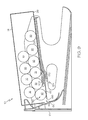
- FIG. 7 is a side elevational view, in section, of the dispenser of the product dispensing system of FIG. 1 ;
- FIG. 8 is a side elevational view, in section, of the dispenser of FIG. 6 , shown with the container in a first, partially loaded configuration;
- FIG. 9 is a side elevational view, in section, of the dispenser of FIG. 7 , shown with the container in a second, fully loaded configuration;
- FIG. 10 is a side elevational view, in section, of the dispenser of FIG. 8 , shown with the container in a third, dispensing configuration.
- one aspect of the disclosed product dispensing system may include a dispenser 12 and a container 14 .
- the container 14 may house multiple units of product 16 .
- the container 14 may be loaded onto the dispenser 12 by urging the container 14 generally horizontally along the dispenser 12 .
- the dispenser 12 may engage and open the container 14 , thereby releasing the products 16 from the container 14 to the dispenser 12 .
- the container 14 may be any container capable of housing products 16 and beneficially interacting with the disclosed dispenser 12 .
- the container 14 may be a paperboard carton or a corrugated box.
- the container 14 may be a generally rectilinear container having six walls 18 , 20 , 22 , 24 , 26 , 28 that define an internal volume 30 for receiving the products 16 ( FIGS. 7 and 8 ).
- Opposed walls 18 and 20 may define the front and rear walls, respectively, of the container 14 .
- Opposed walls 22 and 24 may define the first (e.g., left) and second (e.g., right) side walls, respectively, of the container 14 .
- Opposed walls 26 and 28 may define the base and upper walls, respectively, of the container 14 .
- the base wall 26 of the container 14 may include a removable priming feature 32 , as shown in FIG. 2A .
- the removable priming feature 32 may be removed from the container 14 to reveal an initiation opening 34 that opens into the internal volume 30 of the container 14 .
- the removable priming feature 32 may be positioned such that the initiation opening 34 is formed proximate (i.e., at or near) the rear wall 20 of the container 14 , such as along the edge 44 between the base wall 26 and the rear wall 20 .
- the removable priming feature 32 may be a zipper strip or the like, and may be defined by two parallel, laterally extending rows of perforations or cuts 36 , 38 and two parallel, longitudinally extending rows of perforations or cuts 40 , 42 . Weakening features other than perforations and cuts may also be used.
- a user may remove the removable priming feature 32 from the container 14 , such as by tearing the removable priming feature 32 from the container 14 along the rows of cuts 36 , 38 , 40 , 42 , thereby forming the initiation opening 34 , as shown in FIG. 2B .
- the initiation opening 34 may be pre-formed in the base wall 26 of the container 14 .
- a peelable label or the like (not shown) may be applied to the container 14 over the pre-formed initiation opening 34 . Therefore, the initiation opening 34 may be revealed by peeling away the optional peelable label from the container 14 .
- the initiation opening 34 may extend generally laterally between the side walls 22 , 24 of the container 14 .
- the initiation opening 34 may include a first (e.g., left) end 46 positioned proximate the left side wall 22 of the container 14 and a second (e.g., right) end 48 positioned proximate the right side wall 24 of the container 14 .
- the initiation opening 34 may be positioned at various alternative locations and may have various alternative configurations, provided that the initiation opening 34 is capable of being engaged by the dispenser 12 when the container 14 is being loaded onto the dispenser 12 .
- the initiation opening 34 may be formed in the rear wall 20 of the container 14 .
- the initiation opening 34 may be formed in the base wall 26 , between the front 18 and rear 20 walls of the container 14 .
- Other implementations are also contemplated.
- a first weakening feature 50 may generally longitudinally extend from the initiation opening 34 toward the front wall 18 of the container 14 .
- the first weakening feature 50 may be formed in the base wall 26 proximate the edge 52 between the base wall 26 and the left side wall 22 .
- a second weakening feature 54 may generally longitudinally extend from the initiation opening 34 toward the front wall 18 of the container 14 , and may be laterally spaced from the first weakening feature 50 .
- the second weakening feature 54 may be formed in the base wall 26 proximate the edge 56 between the base wall 26 and the right side wall 24 .
- the longitudinal length of the first and second weakening features 50 , 54 may be dictated by the size (e.g., the diameter) of the products 16 housed in the container 14 .
- the first and second weakening features 50 , 54 may extend along at least 5 percent of the length of the edge 52 .
- the first and second weakening features 50 , 54 may extend along at least 10 percent of the length of the edge 52 .
- the first and second weakening features 50 , 54 may extend along at least 20 percent of the length of the edge 52 .
- the first and second weakening features 50 , 54 may extend along at least 30 percent of the length of the edge 52 .
- the first and second weakening features 50 , 54 may facilitate the separation of a portion of the base wall 26 from the rest of the container 14 , as shown in FIG. 3 .
- the first and second weakening features 50 , 54 may be formed as rows of perforations.
- perforation broadly refers to any structure (or absence of structure) that may be used to form the first and second weakening features 50 , 54 , and includes traditional, generally circular (in plan view) perforations, as well as elongated punctures or cuts.
- the first and second weakening features 50 , 54 may be formed as rows of standard perforations, as rows of micro perforations or as rows of cuts, such as zipper-like cuts. Other techniques useful for forming the first and second weakening features 50 , 54 will become apparent to those skilled in the art.
- the first and second weakening features 50 , 54 may contain rows of generally aligned perforations that may be staggered by a distance D.
- the distance D may be greater than or equal to 0.5 mm, greater than or equal to 1 mm, greater than or equal to 1.5 mm, greater than or equal to 2 mm, or greater than or equal to 3 mm.
- the perforations in the first weakening feature 50 are offset in relation to the perforations in the second weakening feature 54 .
- the perforations in the first and second weakening features 50 , 54 may be formed cuts.
- the cuts may be generally longitudinally extending cuts, as shown in greater detail in FIG. 6 .
- Each cut may further include a longitudinal portion 200 and an angled portion 210 .
- the longitudinal portion 200 may have a length 202 , a first end 204 , and a second end 206 .
- the length 202 may be defined by the distance between the first end 204 and the second end 206 .
- the length 202 may further be any suitable length of a typical zipper-like cut.
- the length 202 may closely correspond to (e.g., be equal to) the staggered distance D ( FIG. 5 ).
- the length 202 may be greater than or equal to 0.5 mm, greater than or equal to 1 mm, greater than or equal to 1.5 mm, greater than or equal to 2 mm, or greater than or equal to 3 mm.
- the angled portion 210 may have a length 212 , a first end 214 , and a second end 216 .
- the length 212 may be defined by the distance between the first end 214 and the second end 216 .
- the length 212 may further be any suitable length of a typical perforation or cut in accordance with the present disclosure. As an example, the length 212 may be greater than or equal to 0.5 mm, greater than or equal to 1 mm, greater than or equal to 1.5 mm, greater than or equal to 2 mm, or greater than or equal to 3 mm.
- the angled portion 210 may extend inward from the second end 206 of the longitudinal portion 200 at a non-zero angle ⁇ relative to the longitudinal axis X of the longitudinal portion 200 .
- the angle ⁇ may be any suitable angle of a typical perforation or cut in accordance with the present disclosure. As an example, the angle ⁇ may be greater than or equal to 20 degrees, greater than or equal to 30 degrees, greater than or equal to 40 degrees, or greater than or equal to 45 degrees.
- the staggered distance D may be measured from the second end 216 of the angled portion 210 of a perforation in the first weakening feature 50 to the second end 216 of the angled portion 210 of a corresponding perforation of the second weakening feature 54 .
- a force F ( FIG. 2B ) applied to the base wall 26 at the initiation opening 34 may partially separate a portion of the base wall 26 from the container 14 along the first and second weakening features 50 , 54 to form an access panel 58 , as shown in FIG. 3 .
- the size of the initiation opening 34 may be significantly increased, thereby forming an access opening 60 in the container 14 .
- the access opening 60 may allow the products 16 housed in the container 14 to be dispensed from the container 14 and, ultimately, into the dispenser 12 when the container 14 is loaded on the dispenser 12 .
- the force F ( FIG. 2B ) applied to the base wall 26 at the initiation opening 34 would be evenly distributed between each corresponding perforation on the first and second weakening features 50 , 54 .
- This even distribution of the force F results in less force directed towards each perforation or cut, and may often result in a need for additional force to break the perforations, which may be difficult for some users.
- the force F is only applied to a perforation on one of the weakening features 50 , 54 at a time (or at least until a tear is initiated).
- the force is directed in an alternating manner between perforations in the first weakening feature 50 and the second weakening feature 54 .
- no force is applied on the other until the first perforation breaks (or at least a tear is initiated in the first perforation).
- the force advances to the next perforation on the other weakening feature. Accordingly, less force is necessary to break the perforations, which may prove easier for some users.
- the container 14 may be formed from a paperboard container blank, such as the paperboard container blank 70 shown in FIG. 4 .
- the container blank 70 may include a plurality of pre-formed fold lines 72 , 74 , 76 , 78 , 71 , 73 that define the front wall 18 (comprised of front wall panels 18 A, 18 B, 18 C and 18 D), the rear wall 20 (comprised of rear wall panels 20 A, 20 B, 20 C and 20 D), the right side wall 24 , the left side wall 22 , the base wall 26 , the upper wall 28 and sealing panel 79 .
- the container 14 may be assembled by folding the container blank 70 along the longitudinal fold lines 72 , 74 , 76 , 78 and connecting the upper wall 28 to the sealing panel 79 to form the three-dimensional body of the container 14 . Then, the front wall panels 18 A, 18 B, 18 C, 18 D may be assembled to form the front wall 18 of the container 14 . Finally, the rear wall panels 20 A, 20 B, 20 D, 20 D may be assembled to form the rear wall 20 of the container 14 .
- the container blank 70 may be formed from a paperboard-based material, such as C1S paperboard, which may have a coating (e.g., clay) on a first major surface thereof, which may form the outer surface 75 ( FIG. 1 ) of the container 14 , and an uncoated second major surface.
- the paperboard-based material may be C2S paperboard, which may have a coating (e.g., clay) on both major surfaces thereof.
- at least one major surface of the container blank may be marked with various indicia 77 ( FIG. 1 ), such as printed text and/or graphics.
- Suitable products 16 having various shapes and configurations may be housed in the container 14 and dispensed by the disclosed product dispensing system 10 .
- Suitable products 16 include cans (e.g., canned soup or pet food), jars (e.g., jarred sauce) or bottles (e.g., bottled soft drinks).
- the dispenser 12 may include a frame 80 and a catch element 82 .
- the frame 80 of the dispenser 12 may support the container 14 in a desired configuration, such as a slightly declined, but generally horizontal configuration, as shown in FIGS. 1 , 9 and 10 .
- the catch element 82 may engage the initiation opening 34 ( FIG. 2B ) in the container 14 to separate the access panel 58 ( FIG. 3 ) from the container 14 , as is described in greater detail herein.
- the frame 80 may include a first (e.g., right) side wall 84 , a second (e.g., left) side wall 86 , an upper support deck 88 and a lower support deck 90 .
- the right side wall 84 may be laterally spaced from the left side wall 86 , and may be generally parallel with the left side wall 86 .
- the frame 80 may include a first (e.g., front) end 92 and a second (e.g., rear) end 94 longitudinally opposed from the first end 92 .
- the lower support deck 90 may laterally extend between the right 84 and left 86 side walls, and may include a front end 96 that longitudinally extends toward the front end 92 of the frame 80 and a rear end 98 that longitudinally extends toward the rear end 94 of the frame 80 . Therefore, the lower support deck 90 and the side walls 84 , 86 may define a lower level 100 of the frame 80 .
- the lower support deck 90 may be inclined from the front end 96 to the rear end 98 (i.e., the rear end 98 may be elevated relative to the front end 96 ) such that products 16 deposited proximate the rear end 98 of the lower support deck 90 roll down to the front end 96 of the lower support deck 90 under the force of gravity.
- the extent of the incline of the lower support deck 90 may be dictated by, among other things, the coefficient of friction of the material used to form the frame 80 and the shape of the products 16 to be dispensed by the dispenser 12 .
- a stop 102 may be positioned proximate the front end 96 of the lower support deck 90 to prevent products 16 from rolling beyond the front end 96 of the lower support deck 90 .
- the stop 102 may be connected to (e.g., integral with) the lower support deck 90 , and may form an upward curve at the front end 96 of the lower support deck 90 . Therefore, the stop 102 may collect products 16 at the front end 96 of the lower support deck 90 , thereby defining a product display area 104 at the front end 96 of the lower support deck 90 .
- the upper support deck 88 may laterally extend between the right 84 and left 86 side walls, and may include a front end 106 that longitudinally extends toward the front end 92 of the frame 80 and a rear end 108 that longitudinally extends toward, but not to, the rear end 94 of the frame 80 . Therefore, the upper support deck 88 and the side walls 84 , 86 may define an upper level 110 of the frame 80 .
- the spacing between the rear end 108 of the upper support deck 88 and the rear end 94 of the frame 80 may define an opening 112 , which may function as a chute to allow products 16 to move from the upper level 110 to the lower level 100 of the frame 80 .
- the access opening 60 ( FIG. 3 ) in the container 14 may be aligned with the opening 112 ( FIG. 5 ) defined by the frame 80 .
- the upper support deck 88 may be declined from the front end 106 to the rear end 108 (i.e., the front end 106 may be elevated relative to the rear end 108 ). Therefore, products 16 supported on the upper support deck 88 may roll under the force of gravity down to the rear end 108 of the upper support deck 88 , through the opening 112 , to the lower level 100 of the frame 80 and, ultimately, to the product display area 104 .
- An optional rear wall 114 may be positioned proximate the rear end 94 of the frame 80 between the right 84 and left 86 side walls.
- the rear wall 114 may serve as a stop that inhibits rearward horizontal movement of the container 14 ( FIG. 1 ) along the upper support deck 88 beyond the rear wall 114 .
- a guide 116 may be connected to the rear wall 114 of the frame 80 , and may extend through the opening 112 in the frame 80 , from the upper level 110 to the lower level 100 .
- the guide 116 may be a ramp-like structure, and may be positioned to receive products 16 exiting the container 14 and passing through the opening 112 in the frame 80 , and may guide the products 16 to the rear end 98 of the lower support deck 90 .
- the catch element 82 may be positioned between the front end 106 and the rear end 108 of the upper support deck 88 .
- the catch element 82 may be positioned proximate the rear end 108 of the upper support deck 88 .
- the catch element 82 may laterally extend between the side walls 84 , 86 of the frame 80 , and may longitudinally protrude toward the front end 92 of the frame 80 .
- the specific size and shape of the catch element 82 may depend on the size and shape of the initiation opening 34 in the container 14 .
- the catch element 82 may be substantially co-planar with the upper surface 118 of the upper support deck 88 .
- the catch element 82 may be substantially co-planar with the upper surface 118 of the upper support deck 88 .
- slight displacement and/or a slight angle of the catch element 82 relative to the upper surface 118 of the upper support deck 88 may encourage engagement of the initiation opening 34 in the container 14 by the catch element 82 during loading of the container 14 onto the dispenser 12 .
- catch element 82 is shown and described as a generally flat, laterally elongated and forwardly extending protrusion, those skilled in the art will appreciate that various alternative structures may be used as the disclosed catch element 82 without departing from the scope of the present disclosure.
- suitable catch elements may include various hooks, protrusions, flanges, detents and the like sufficient to engage the initiation opening 34 in the container 14 and separate the access panel 58 from the base wall 26 of the container 14 .
- the upper support deck 88 may define a channel 120 positioned to guide the access panel 58 below the upper surface 118 of the upper support deck 88 as the access panel 58 is separated from the container 14 by the catch element 82 .
- the channel 120 may extend from an entrance opening 122 proximate the catch element 82 , down below the catch element 82 and, ultimately, to an exit opening 124 .
- the channel 120 may laterally extend between the side walls 84 , 86 of the frame 80 , and may have a lateral width sufficient to allow the access panel 58 ( FIG. 3 ) to pass therethrough.
- the channel 120 may move longitudinally along the support deck 88 from the rear end 94 to the front end 92 ( FIG. 10 ).
- the catch element 82 may engage the initiation opening 34 ( FIG. 2B ) in the container 14 and may separate the access panel 58 ( FIG. 3 ) from the container 14 as the container 14 is moved horizontally along the upper support deck 88 toward the rear end 94 of the frame 80 .
- the shape and position of the catch element 82 may be configured such that a portion of the catch element 82 extends through the initiation opening 34 ( FIG. 2B ) in the container 14 . Therefore, as the container 14 moves relative to the catch element 82 , the catch element 82 may urge the base wall 26 downward through the opening 122 and into the channel 120 , thereby causing separating of the access panel 58 ( FIG. 3 ) from the container 14 along the first and second weakening features 50 , 54 ( FIG. 2B ) and, ultimately, the formation of the access opening 60 ( FIG. 3 ) in the container 14 .
- FIGS. 7-9 illustrate the container 14 being loaded onto the dispenser 12 such that the catch element 82 of the dispenser 12 engages and opens the container 14 , thereby releasing the products 16 initially housed in the container 14 to the dispenser 12 .
- FIGS. 7-9 illustrate the container 14 being urged generally horizontally along the upper support deck 88 (i.e., along the longitudinal axis A of the upper support deck 88 ) toward the rear end 94 of the dispenser frame 80 , thereby automatically opening the container 14 and dispensing the products 16 from the container 14 to the dispenser 12 .
- the catch element 82 may pass through the initiation opening 34 .
- the rear edge 66 of the base wall 26 of the container 14 may be directed downward through the entrance opening 122 of the channel 120 .
- the base wall 26 of the container 14 may pass through the channel 120 , thereby separating the access panel 58 from the base wall 26 .
- the access opening 60 formed in the container 14 may be aligned with the opening 112 between upper 110 and lower 100 levels of the frame 80 . Therefore, the force of gravity may urge the products 16 initially housed in the container 14 through the access opening 60 in the container 14 , through the opening 112 in the frame 80 , down to the lower support deck 90 and, ultimately, to the product display area 104 .
- staggered perforations as described herein may provide one or more advantageous methods of forming the access panel. Such methods may be advantageous because the perforations may be more likely than the prior art to separate when a force is provided. Additionally, such methods may be advantageous because less of a force may be necessary to separate the perforations than what was required in the past. Other advantages may also become apparent to those skilled in the art.
Abstract
Description
Claims (19)
Priority Applications (4)
| Application Number | Priority Date | Filing Date | Title |
|---|---|---|---|
| US13/404,171 US8833601B2 (en) | 2012-02-24 | 2012-02-24 | Product dispensing system with staggered perforations |
| PCT/US2013/025261 WO2013126218A1 (en) | 2012-02-24 | 2013-02-08 | Product dispensing system with staggered perforations |
| TW102105715A TW201335036A (en) | 2012-02-24 | 2013-02-19 | Product dispensing system with staggered perforations |
| ARP130100558A AR090137A1 (en) | 2012-02-24 | 2013-02-25 | PRODUCT DISPENSER SYSTEM WITH SCALE DRILLS |
Applications Claiming Priority (1)
| Application Number | Priority Date | Filing Date | Title |
|---|---|---|---|
| US13/404,171 US8833601B2 (en) | 2012-02-24 | 2012-02-24 | Product dispensing system with staggered perforations |
Publications (2)
| Publication Number | Publication Date |
|---|---|
| US20130221017A1 US20130221017A1 (en) | 2013-08-29 |
| US8833601B2 true US8833601B2 (en) | 2014-09-16 |
Family
ID=47754990
Family Applications (1)
| Application Number | Title | Priority Date | Filing Date |
|---|---|---|---|
| US13/404,171 Active 2032-03-27 US8833601B2 (en) | 2012-02-24 | 2012-02-24 | Product dispensing system with staggered perforations |
Country Status (4)
| Country | Link |
|---|---|
| US (1) | US8833601B2 (en) |
| AR (1) | AR090137A1 (en) |
| TW (1) | TW201335036A (en) |
| WO (1) | WO2013126218A1 (en) |
Cited By (5)
| Publication number | Priority date | Publication date | Assignee | Title |
|---|---|---|---|---|
| US20150001244A1 (en) * | 2013-08-29 | 2015-01-01 | Giraffx Design, LLC | Dispenser with wedge for rolling products |
| US20150053754A1 (en) * | 2013-08-22 | 2015-02-26 | Meadwestvaco Corporation | Product Dispensing System with Reinforced Weakening Features |
| US20160058204A1 (en) * | 2014-08-26 | 2016-03-03 | Menasha Corporation | Can Dispenser |
| US20160262554A1 (en) * | 2015-03-11 | 2016-09-15 | Mark VITOLLO | Can Dispenser And Merchandiser |
| US11508202B1 (en) * | 2021-03-22 | 2022-11-22 | Henschel-Steinau, Inc. | Modular display and dispensing system |
Families Citing this family (3)
| Publication number | Priority date | Publication date | Assignee | Title |
|---|---|---|---|---|
| US9174785B2 (en) * | 2011-02-23 | 2015-11-03 | Westrock Mwv, Llc | Product dispensing system with panel guide |
| US20140076922A1 (en) * | 2012-09-20 | 2014-03-20 | Meadwestvaco Corporation | Product Dispensing System with Increased Container and Dispenser Openings |
| US8955695B2 (en) | 2013-03-14 | 2015-02-17 | Giraffx Design, LLC | Serpentine dispenser with cartridges |
Citations (179)
| Publication number | Priority date | Publication date | Assignee | Title |
|---|---|---|---|---|
| US902347A (en) | 1903-01-17 | 1908-10-27 | Benjamin C Tillinghast | Vending carton or package. |
| US1291420A (en) | 1918-07-05 | 1919-01-14 | Adoniram Bird Cough | Cabinet for stores and shops. |
| US1383318A (en) | 1919-09-29 | 1921-07-05 | Robert R Mccormick | Paper-roll storage and delivery gallery |
| US1393964A (en) | 1917-11-03 | 1921-10-18 | Autosales Corp | Vending-machine indicator |
| US1753957A (en) | 1928-02-01 | 1930-04-08 | Beech Nut Packing Co | Distributing device |
| US1824937A (en) | 1930-10-31 | 1931-09-29 | Independent Oil Well Cementing | Sack severing device |
| US1898056A (en) | 1930-07-23 | 1933-02-21 | Chicago Carton Co | Dispensing carton |
| US1919907A (en) | 1932-04-21 | 1933-07-25 | Clyde J Robinson | Package opener |
| US1932225A (en) | 1933-04-22 | 1933-10-24 | Minter Hugh | Automatic conveyer truck |
| US1941458A (en) | 1933-06-03 | 1934-01-02 | Samuel J Bens | Pack holder and cutter |
| US1985739A (en) | 1933-08-18 | 1934-12-25 | Murray Paul | Vehicle body for barrels |
| US2078599A (en) | 1936-06-16 | 1937-04-27 | George L Blaxton | Cement sack opening device |
| US2110194A (en) | 1937-01-29 | 1938-03-08 | Maurice E Blier | Package opener |
| US2263353A (en) | 1940-11-04 | 1941-11-18 | Eidam Adam | Box opener |
| US2291187A (en) | 1941-05-16 | 1942-07-28 | Benjamin F Johnson | Match box dispenser |
| US2382191A (en) | 1944-07-05 | 1945-08-14 | Walter W Weichselbaum | Dispensing device |
| US2536421A (en) | 1948-05-19 | 1951-01-02 | Eugene C Burhans | Carton opener |
| US2573381A (en) | 1949-05-27 | 1951-10-30 | Edward F Arnold | Cutting device |
| US2574087A (en) | 1947-10-29 | 1951-11-06 | Eugene C Burhans | Carton handling device |
| US2595122A (en) | 1950-07-19 | 1952-04-29 | Eugene C Burhans | Carton opener |
| US2784871A (en) | 1952-06-07 | 1957-03-12 | Rowe Mfg Co Inc | Empty signal for columnar merchandising machines |
| US2795845A (en) | 1956-03-30 | 1957-06-18 | Ernest E Shimer | Carton opening machine |
| US2818978A (en) | 1954-03-01 | 1958-01-07 | Jack C Post | Barrel rack |
| US2826471A (en) | 1953-09-22 | 1958-03-11 | Gen Electric | Frozen fruit juice dispenser |
| US2831591A (en) | 1956-12-06 | 1958-04-22 | Rohm & Haas | Bulk package opener |
| US2888145A (en) | 1953-12-30 | 1959-05-26 | Knott Joseph Fred | Bin dispenser |
| US2915932A (en) | 1957-01-15 | 1959-12-08 | Union Bag Camp Paper Corp | Device for simultaneously cutting the corners of a box to provide closure flaps |
| US2919488A (en) | 1958-03-10 | 1960-01-05 | Meyercord Co | Carton slitting device |
| US2996344A (en) | 1958-02-05 | 1961-08-15 | Owens Illinois Glass Co | Dispensing carton |
| US3018149A (en) | 1957-02-28 | 1962-01-23 | John T Parker | Storage container for uniform sized articles |
| US3055293A (en) | 1960-08-05 | 1962-09-25 | Michael J Lariccia | Storage and dispensing rack for cans and the like |
| US3066827A (en) | 1960-01-11 | 1962-12-04 | Nat Vendors Inc | Article vending machine |
| US3137068A (en) | 1961-01-03 | 1964-06-16 | James B Quigley | Carton-slitting mechanism |
| US3178242A (en) * | 1963-05-13 | 1965-04-13 | Anheuser Busch | One-piece dispensing carton for cylindrical objects |
| US3184104A (en) | 1963-12-05 | 1965-05-18 | Golden Grain Macaroni Co | Dispenser |
| US3203554A (en) | 1964-01-27 | 1965-08-31 | Southern Spring Bed Company | Can carton rack |
| US3204335A (en) | 1963-08-16 | 1965-09-07 | John W Hughes | Paper carton cutter |
| US3288544A (en) | 1963-11-20 | 1966-11-29 | Wintercorn Andrew F | Combination merchandise display and storage unit |
| US3300115A (en) | 1965-04-05 | 1967-01-24 | Boise Cascade Corp | Compartmented dispensing carton formed from a single blank |
| US3304141A (en) | 1965-02-04 | 1967-02-14 | Rogers Kenneth | Roller rack |
| US3318455A (en) | 1965-08-30 | 1967-05-09 | Century Display Mfg Corp | Dispensing rack |
| US3335940A (en) | 1966-03-31 | 1967-08-15 | Container Corp | Reclosable carrier-dispensing container |
| US3340790A (en) | 1965-11-22 | 1967-09-12 | Gen Res Inc | Dispensing apparatus |
| US3348738A (en) | 1965-12-21 | 1967-10-24 | Gen Refractories Co | Dispensing hopper having a container opener |
| US3392901A (en) | 1966-09-14 | 1968-07-16 | Milprint Inc | End closure for a combination package |
| US3393808A (en) | 1965-10-07 | 1968-07-23 | Sam N. Chirchill | Apparatus for storing, displaying and dispensing articles |
| US3501016A (en) | 1968-02-05 | 1970-03-17 | Kenneth C Eaton | Article storage apparatus |
| US3763557A (en) | 1972-01-04 | 1973-10-09 | C Sewell | Automatic carton opener |
| US3784022A (en) | 1972-03-22 | 1974-01-08 | W Beesley | Portable and disposable dispensing packages |
| US3923159A (en) | 1974-09-16 | 1975-12-02 | Lake Chemical Co | Product display and article dispensing device |
| US3922778A (en) | 1973-04-13 | 1975-12-02 | Arenco Pmb Bv | Device for cutting the sidewalls of a box for separating wholly or partly the lid from the box proper |
| US3972454A (en) | 1975-07-31 | 1976-08-03 | Comco, Inc. | Drum-like fiberboard container for bulk material with frangible bottom closure for dispensing |
| US4105126A (en) | 1976-08-05 | 1978-08-08 | Visual Marketing, Inc. | Storage and dispensing rack |
| US4205440A (en) | 1978-11-28 | 1980-06-03 | Morgan Jerry A | Package opener arrangement |
| US4260072A (en) | 1980-02-26 | 1981-04-07 | Quasarano Joseph R | Shipping, transporting and dispensing container for cylindrically shaped objects |
| US4382526A (en) | 1979-04-24 | 1983-05-10 | Pack Image Incorporated | Dispensing container and blanks therefor |
| US4396143A (en) * | 1981-08-31 | 1983-08-02 | Manville Service Corporation | Multiple article beverage package |
| US4435026A (en) | 1982-06-07 | 1984-03-06 | Johnson Michael R | Modular stacking trays |
| US4467524A (en) | 1983-01-24 | 1984-08-28 | Stanley Ruff | Corrugated carton cutter |
| US4511043A (en) * | 1983-09-19 | 1985-04-16 | Champion International Corporation | Easy opening carton |
| US4576272A (en) | 1984-06-21 | 1986-03-18 | The Coca-Cola Company | Counter-top or wall-mounted vending machine |
| US4598828A (en) | 1983-02-22 | 1986-07-08 | Visual Marketing, Inc. | Storage and dispensing rack |
| US4729480A (en) | 1986-08-18 | 1988-03-08 | The Coca-Cola Company | Expanded capacity vend basket for a vending machine |
| US4744489A (en) | 1985-11-22 | 1988-05-17 | Tone Brothers, Inc. | Store display fixture |
| US4834263A (en) | 1986-09-05 | 1989-05-30 | Thomas Becze | Tamper resistant apparatus for dispensing packaged products |
| US4869395A (en) | 1987-05-19 | 1989-09-26 | Aktiebolaget Electrolux | Vending machine with interchangeable magazines |
| GB2190906B (en) | 1986-05-23 | 1989-12-13 | Sean Durkan | A device for storing and dispensing cans or the like |
| US4911309A (en) | 1988-08-25 | 1990-03-27 | Alexander Stefan | Storage rack for cylindrical cans |
| US4915571A (en) | 1986-05-12 | 1990-04-10 | Sanden Corporation | Device for loading cans, bottles, or the like into a dispensing mechanism |
| US4923070A (en) | 1985-11-15 | 1990-05-08 | The Niven Marketing Group | Display and gravity dispensing apparatus |
| US4997106A (en) | 1989-10-19 | 1991-03-05 | Rock-Ola Manufacturing Corporation | Storage magazine and feed system for vending cylindrical articles |
| US4998628A (en) | 1989-04-17 | 1991-03-12 | Roll-A-Bot, Inc. | Gravity-operated bottle and can dispensing rack |
| JPH03105494A (en) | 1989-09-19 | 1991-05-02 | Mead Toppan Kk | Automatic vending machine |
| WO1991006076A1 (en) | 1989-10-12 | 1991-05-02 | The Mead Corporation | Automatic vending machine |
| JPH03133737A (en) | 1989-10-12 | 1991-06-06 | Mead Corp:The | Wrapping container |
| US5033348A (en) | 1988-11-04 | 1991-07-23 | J&M Engineering Corporation | Box cutting machine |
| JPH03198192A (en) | 1989-12-27 | 1991-08-29 | Katsuhiro Nakamura | Loader for feeding canned drink into automatic vending machine |
| JPH03273477A (en) | 1990-03-23 | 1991-12-04 | Sanyo Electric Co Ltd | Automatic vending machine |
| JPH03273476A (en) | 1990-03-23 | 1991-12-04 | Sanyo Electric Co Ltd | Automatic vending machine |
| JPH03273471A (en) | 1990-03-23 | 1991-12-04 | Sanyo Electric Co Ltd | Commodity loading device |
| JPH03273469A (en) | 1990-03-23 | 1991-12-04 | Sanyo Electric Co Ltd | Commodity storage device for automatic vending machine |
| JPH03273482A (en) | 1990-03-23 | 1991-12-04 | Sanyo Electric Co Ltd | Automatic vending machine |
| JPH03273470A (en) | 1990-03-23 | 1991-12-04 | Sanyo Electric Co Ltd | Automatic vending machine |
| JPH03273483A (en) | 1990-03-23 | 1991-12-04 | Sanyo Electric Co Ltd | Automatic vending machine |
| JPH03273474A (en) | 1990-03-23 | 1991-12-04 | Sanyo Electric Co Ltd | Automatic vending machine |
| JPH03273472A (en) | 1990-03-23 | 1991-12-04 | Sanyo Electric Co Ltd | Automatic vending machine |
| JPH03273480A (en) | 1990-03-23 | 1991-12-04 | Sanyo Electric Co Ltd | Automatic vending machine |
| US5080256A (en) | 1990-01-18 | 1992-01-14 | Rock-Ola Manufacturing Corporation | Slant shelf magazine for automatic vending machines |
| JPH0486985A (en) | 1990-07-31 | 1992-03-19 | Kiyougo Hoshino | Chuter for automatic vending machine |
| US5097958A (en) * | 1990-10-19 | 1992-03-24 | Somerville Packaging, A Division Of Paperboard Industries | Carton and blank and method of forming the carton from a blank |
| US5101703A (en) | 1988-09-08 | 1992-04-07 | Kao Corporation | Box cutting method and apparatus thereof |
| JPH04115392A (en) | 1990-09-05 | 1992-04-16 | Kubota Corp | Commodity replenishing jig for automatic vending machine |
| JPH04137194A (en) | 1990-09-28 | 1992-05-12 | Kubota Corp | Automatic vending machine |
| JPH04157593A (en) | 1990-10-22 | 1992-05-29 | Sanyo Electric Co Ltd | Merchandise supply device for automatic vending machine |
| US5167345A (en) | 1991-07-25 | 1992-12-01 | Bobrick Washroom Equipment, Inc. | Dual dispenser |
| JPH054640A (en) | 1991-01-30 | 1993-01-14 | Sharp Corp | Article replenishing packing case and method for placing the same case into automatic vending machine |
| JPH05174239A (en) | 1991-07-08 | 1993-07-13 | Fuji Electric Co Ltd | Automatic vending machine |
| US5251972A (en) | 1991-12-31 | 1993-10-12 | Michael Zurawin | Device for displaying and dispensing consumer products on shelving |
| JPH05346984A (en) | 1991-04-18 | 1993-12-27 | Imazato Akira | Method for handling bottled or canned product and take-out instrument, packing member, and mount base used for method |
| US5289943A (en) | 1992-04-20 | 1994-03-01 | Powell Philip M | Holder for dispensing cans from a multi-can carton |
| US5314078A (en) | 1991-09-06 | 1994-05-24 | Tsubakimoto Chain Co. | First-in first-out article storage rack apparatus |
| US5328258A (en) | 1992-09-08 | 1994-07-12 | Scalise Guy G | Pizza box storage and dispensing assembly |
| US5356033A (en) | 1992-12-01 | 1994-10-18 | David Delaney | Beverage dispensing method and apparatus |
| US5372278A (en) | 1993-04-27 | 1994-12-13 | Leight; Howard S. | Earplug dispenser box |
| US5390821A (en) | 1994-02-04 | 1995-02-21 | Markel; Stephen M. | Method and apparatus for dispensing rollable articles |
| US5396997A (en) | 1993-10-19 | 1995-03-14 | Oscar Mayer Foods Corporation | Self-facing, multi-container refrigerator display apparatus |
| USD363174S (en) | 1994-11-04 | 1995-10-17 | Fletcher Sr Richard M | Storing and dispensing apparatus |
| US5462198A (en) | 1994-03-23 | 1995-10-31 | Miles Inc. | Modular bottle dispenser |
| JPH08161611A (en) | 1994-12-07 | 1996-06-21 | Takeuchi Press Ind Co Ltd | Jig for replenishing canned beverage |
| US5529207A (en) | 1995-01-25 | 1996-06-25 | Royal Vendors, Inc. | Adjustable retainer system for vending machine storage compartments |
| JPH0927066A (en) | 1995-07-12 | 1997-01-28 | Sanyo Electric Co Ltd | Automatic vending machine |
| US5598920A (en) * | 1995-08-03 | 1997-02-04 | Rieber & Son A/S | Carrier for carrying several bottles |
| GB2303624A (en) | 1995-07-28 | 1997-02-26 | Kraft Jacobs Suchard Limited | Serpentine dispenser |
| JPH09102065A (en) | 1995-10-05 | 1997-04-15 | Morishiyou:Kk | Tool capable of easily putting can (bottle) juice (beer) in automatic multiple kind vending machine |
| US5638988A (en) | 1995-12-22 | 1997-06-17 | Loveland Industries, Inc. | Particulate dispensing system |
| JPH09282537A (en) | 1996-04-15 | 1997-10-31 | Katsuhiko Togashi | Canned beverage replenisher for automatic vending machine |
| US5685664A (en) | 1995-06-13 | 1997-11-11 | The Mead Corporation | Arrangement for interconnecting two objects |
| JPH09311971A (en) | 1996-05-23 | 1997-12-02 | Kawayoshi:Kk | Bottle and can carry-out attachment for bottle and can package |
| US5740610A (en) | 1993-08-23 | 1998-04-21 | General Housewares Corp. | Carton opener |
| US5788117A (en) | 1996-07-17 | 1998-08-04 | Zimmanck; Jack | Beverage can dispenser |
| JPH10269421A (en) | 1997-03-26 | 1998-10-09 | Kimura Koji | Canned beverage shooter for automatic vending machine |
| US5836478A (en) | 1997-02-28 | 1998-11-17 | Atico International Usa, Inc. | Battery dispenser |
| JPH1111471A (en) | 1997-02-25 | 1999-01-19 | Keiji Kuratani | Container storage box for drink or the like, and container leading device for drink or the like |
| US5878862A (en) | 1997-12-15 | 1999-03-09 | Ledan, Inc. | Product delivery device |
| US5894942A (en) | 1997-05-28 | 1999-04-20 | Yazaki Industrial Chemical Co Ltd. | Gravity feed flow-rack apparatus |
| JPH11171264A (en) | 1997-12-12 | 1999-06-29 | Hiroyuki Nohara | Container storage box and container lead-out jig |
| JPH11191175A (en) | 1997-12-25 | 1999-07-13 | Ki Planning Kk | Can throwing device for automatic vending machine |
| JPH11328513A (en) | 1998-05-08 | 1999-11-30 | Koto Plastics Kogyo Kk | Can feeder |
| US5992652A (en) | 1997-07-30 | 1999-11-30 | Newell Operating Company | Refill indicator for product display and dispensing system |
| US5992286A (en) | 1997-02-14 | 1999-11-30 | Boole; Leon | Apparatus for opening coin wrappers |
| US6186345B1 (en) | 1998-10-21 | 2001-02-13 | Display Industires, Llc. | Stackable shipping case having gravity feed tracks |
| US6199720B1 (en) | 1998-03-20 | 2001-03-13 | The Coca-Cola Company | Vending machine |
| JP2001072076A (en) | 1999-09-07 | 2001-03-21 | Tsukasa Ogasawara | Seeing-through hole mediation plate case |
| US6206237B1 (en) | 1999-03-08 | 2001-03-27 | Pepsico, Inc. | Bottle dispenser |
| US6253930B1 (en) | 1997-08-08 | 2001-07-03 | General Cable Technologies Corporation | Dispensing carton assembly |
| US6267258B1 (en) | 1999-05-07 | 2001-07-31 | Gilmour, Inc. | Gravity feed pull out shelf with rear storage area and associated method for displaying and storing a product |
| JP2001206358A (en) | 2000-01-24 | 2001-07-31 | Oji Paper Co Ltd | Paper overwrapping case |
| US20020043509A1 (en) | 2000-10-12 | 2002-04-18 | Andre Lajeunesse | Water bottle rack |
| US6393799B2 (en) | 2000-01-10 | 2002-05-28 | Stuart M. Jenkins | Coin box cassette loading system |
| US6453641B1 (en) | 1997-12-22 | 2002-09-24 | National Scientific Company | Replaceable cap supply cartridge |
| US6637604B1 (en) | 2002-05-23 | 2003-10-28 | Display Technologies, Llc | Dispensing tray with drop product rotation |
| JP2003327243A (en) | 2002-05-09 | 2003-11-19 | Rengo Co Ltd | Packaging box |
| JP2004017970A (en) | 2002-06-12 | 2004-01-22 | Mead Corp:The | Carton |
| US20040011751A1 (en) | 2002-08-20 | 2004-01-22 | Johnson Terry J. | Multi-chute gravity feed dispenser display |
| US6802433B2 (en) | 2002-09-11 | 2004-10-12 | Lhd Vending, Inc. | Food dispensing machine and method of use |
| WO2004113808A1 (en) | 2003-06-20 | 2004-12-29 | Australasian Sign Company Pty Ltd | An improved packaged beverage refrigerator |
| US20040262326A1 (en) | 2003-06-25 | 2004-12-30 | Christensen Coston L. | Selectively cascadeable storage management apparatus, method, and system |
| US20050127015A1 (en) | 2003-12-11 | 2005-06-16 | Excell Products, Inc. | Modular storage and dispensing assembly |
| US20050207877A1 (en) | 2004-03-18 | 2005-09-22 | Haverdink Virgil D | Seed cotton handling system |
| JP2005338910A (en) | 2004-05-24 | 2005-12-08 | Shigeru Ogata | Package for supplying product to automatic vending machine |
| US20060081692A1 (en) | 2004-10-20 | 2006-04-20 | The Coca-Cola Company | Carton with article opening |
| US20060237384A1 (en) | 2005-04-20 | 2006-10-26 | Eric Neumann | Track unit with removable partitions |
| US20060278591A1 (en) | 2005-06-08 | 2006-12-14 | Tippets Michael A | First in, first out, gravity-feed can organizer |
| US7163139B2 (en) * | 2002-02-08 | 2007-01-16 | Meadwestvaco Packaging Systems, Llc | Carton and carton blank |
| US7303095B2 (en) | 2004-12-21 | 2007-12-04 | Alpha Security Products, Inc. | Merchandise dispenser with time delay |
| US20080245813A1 (en) | 2002-08-20 | 2008-10-09 | Johnson Terry J | Multi-chute gravity feed dispenser display |
| US7445114B2 (en) * | 2006-02-08 | 2008-11-04 | Illinois Tool Works, Inc. | Divisible container carrier |
| US7546973B2 (en) | 2000-11-16 | 2009-06-16 | Georgia-Pacific Consumer Products Lp | Low reserve indicator for a paper towel dispenser |
| US20090212066A1 (en) | 2008-02-25 | 2009-08-27 | Jamie Bauer | Product dispenser assembly and cartridge for holding product |
| US7584854B2 (en) | 2005-10-20 | 2009-09-08 | Kitaru Innovations Inc. | Shipping and display assembly for complementary products |
| US20090266776A1 (en) | 2008-04-25 | 2009-10-29 | Johnson Terry J | Dispenser and Display Device |
| WO2009138538A1 (en) | 2008-05-14 | 2009-11-19 | Microtiker, S.L. | Apparatus for the automatic dispensing and semi-automatic repositioning of commercial products |
| USD604972S1 (en) | 2007-03-06 | 2009-12-01 | Mccormick & Company, Inc. | Gravity fed dispenser |
| US7648060B2 (en) * | 2004-11-03 | 2010-01-19 | Graphic Packaging International, Inc. | Carton having opening features |
| US20100032391A1 (en) | 2008-05-14 | 2010-02-11 | Display Technologies | Priduct display unit with adjustable width |
| US7665618B2 (en) | 2005-03-01 | 2010-02-23 | Richard Jay | Product dispenser track assembly |
| US7673789B2 (en) * | 2005-07-22 | 2010-03-09 | Graphic Packaging International, Inc. | Carton with opening feature and blank |
| US7681745B2 (en) | 2002-09-06 | 2010-03-23 | Dci Marketing, Inc. | Merchandising system |
| US7810672B1 (en) | 2007-01-04 | 2010-10-12 | New Dimensions Research Corporation | Display device |
| US7823733B2 (en) | 2006-03-31 | 2010-11-02 | System Communications, Inc. | Article display tray provided with movement guide device, and movement guide device |
| US7850015B1 (en) | 2007-01-04 | 2010-12-14 | New Dimensions Research Corporation | Display device for tubular items |
| US7913860B2 (en) | 2007-10-08 | 2011-03-29 | Merl Milton J | Gravity-fed storage and dispensing unit |
| US7918365B2 (en) | 2006-09-18 | 2011-04-05 | Display Industries, Llc | Bottle display and dispenser device and method |
| US7922437B1 (en) * | 2009-11-23 | 2011-04-12 | Meadwestvaco Corporation | Display system, dispensing device and package for use therein |
| US7938312B2 (en) * | 2006-01-17 | 2011-05-10 | Graphic Packaging International, Inc. | Carton with bag closures |
| US20110121011A1 (en) * | 2009-11-23 | 2011-05-26 | John Gelardi | Product Dispensing System With Anti-Theft Engagement |
| US8302809B1 (en) * | 2011-05-11 | 2012-11-06 | Meadwestvaco Corporation | Product dispensing system with increased product-to-dispenser contact |
| US8308023B2 (en) * | 2011-02-23 | 2012-11-13 | Meadwestvaco Corporation | Product dispensing system with directional flexing container |
| US8322543B2 (en) * | 2010-07-23 | 2012-12-04 | Meadwestvaco Corporation | Product dispensing apparatus and system |
-
2012
- 2012-02-24 US US13/404,171 patent/US8833601B2/en active Active
-
2013
- 2013-02-08 WO PCT/US2013/025261 patent/WO2013126218A1/en active Application Filing
- 2013-02-19 TW TW102105715A patent/TW201335036A/en unknown
- 2013-02-25 AR ARP130100558A patent/AR090137A1/en unknown
Patent Citations (185)
| Publication number | Priority date | Publication date | Assignee | Title |
|---|---|---|---|---|
| US902347A (en) | 1903-01-17 | 1908-10-27 | Benjamin C Tillinghast | Vending carton or package. |
| US1393964A (en) | 1917-11-03 | 1921-10-18 | Autosales Corp | Vending-machine indicator |
| US1291420A (en) | 1918-07-05 | 1919-01-14 | Adoniram Bird Cough | Cabinet for stores and shops. |
| US1383318A (en) | 1919-09-29 | 1921-07-05 | Robert R Mccormick | Paper-roll storage and delivery gallery |
| US1753957A (en) | 1928-02-01 | 1930-04-08 | Beech Nut Packing Co | Distributing device |
| US1898056A (en) | 1930-07-23 | 1933-02-21 | Chicago Carton Co | Dispensing carton |
| US1824937A (en) | 1930-10-31 | 1931-09-29 | Independent Oil Well Cementing | Sack severing device |
| US1919907A (en) | 1932-04-21 | 1933-07-25 | Clyde J Robinson | Package opener |
| US1932225A (en) | 1933-04-22 | 1933-10-24 | Minter Hugh | Automatic conveyer truck |
| US1941458A (en) | 1933-06-03 | 1934-01-02 | Samuel J Bens | Pack holder and cutter |
| US1985739A (en) | 1933-08-18 | 1934-12-25 | Murray Paul | Vehicle body for barrels |
| US2078599A (en) | 1936-06-16 | 1937-04-27 | George L Blaxton | Cement sack opening device |
| US2110194A (en) | 1937-01-29 | 1938-03-08 | Maurice E Blier | Package opener |
| US2263353A (en) | 1940-11-04 | 1941-11-18 | Eidam Adam | Box opener |
| US2291187A (en) | 1941-05-16 | 1942-07-28 | Benjamin F Johnson | Match box dispenser |
| US2382191A (en) | 1944-07-05 | 1945-08-14 | Walter W Weichselbaum | Dispensing device |
| US2574087A (en) | 1947-10-29 | 1951-11-06 | Eugene C Burhans | Carton handling device |
| US2536421A (en) | 1948-05-19 | 1951-01-02 | Eugene C Burhans | Carton opener |
| US2573381A (en) | 1949-05-27 | 1951-10-30 | Edward F Arnold | Cutting device |
| US2595122A (en) | 1950-07-19 | 1952-04-29 | Eugene C Burhans | Carton opener |
| US2784871A (en) | 1952-06-07 | 1957-03-12 | Rowe Mfg Co Inc | Empty signal for columnar merchandising machines |
| US2826471A (en) | 1953-09-22 | 1958-03-11 | Gen Electric | Frozen fruit juice dispenser |
| US2888145A (en) | 1953-12-30 | 1959-05-26 | Knott Joseph Fred | Bin dispenser |
| US2818978A (en) | 1954-03-01 | 1958-01-07 | Jack C Post | Barrel rack |
| US2795845A (en) | 1956-03-30 | 1957-06-18 | Ernest E Shimer | Carton opening machine |
| US2831591A (en) | 1956-12-06 | 1958-04-22 | Rohm & Haas | Bulk package opener |
| US2915932A (en) | 1957-01-15 | 1959-12-08 | Union Bag Camp Paper Corp | Device for simultaneously cutting the corners of a box to provide closure flaps |
| US3018149A (en) | 1957-02-28 | 1962-01-23 | John T Parker | Storage container for uniform sized articles |
| US2996344A (en) | 1958-02-05 | 1961-08-15 | Owens Illinois Glass Co | Dispensing carton |
| US2919488A (en) | 1958-03-10 | 1960-01-05 | Meyercord Co | Carton slitting device |
| US3066827A (en) | 1960-01-11 | 1962-12-04 | Nat Vendors Inc | Article vending machine |
| US3055293A (en) | 1960-08-05 | 1962-09-25 | Michael J Lariccia | Storage and dispensing rack for cans and the like |
| US3137068A (en) | 1961-01-03 | 1964-06-16 | James B Quigley | Carton-slitting mechanism |
| US3178242A (en) * | 1963-05-13 | 1965-04-13 | Anheuser Busch | One-piece dispensing carton for cylindrical objects |
| US3204335A (en) | 1963-08-16 | 1965-09-07 | John W Hughes | Paper carton cutter |
| US3288544A (en) | 1963-11-20 | 1966-11-29 | Wintercorn Andrew F | Combination merchandise display and storage unit |
| US3184104A (en) | 1963-12-05 | 1965-05-18 | Golden Grain Macaroni Co | Dispenser |
| US3203554A (en) | 1964-01-27 | 1965-08-31 | Southern Spring Bed Company | Can carton rack |
| US3304141A (en) | 1965-02-04 | 1967-02-14 | Rogers Kenneth | Roller rack |
| US3300115A (en) | 1965-04-05 | 1967-01-24 | Boise Cascade Corp | Compartmented dispensing carton formed from a single blank |
| US3318455A (en) | 1965-08-30 | 1967-05-09 | Century Display Mfg Corp | Dispensing rack |
| US3393808A (en) | 1965-10-07 | 1968-07-23 | Sam N. Chirchill | Apparatus for storing, displaying and dispensing articles |
| US3340790A (en) | 1965-11-22 | 1967-09-12 | Gen Res Inc | Dispensing apparatus |
| US3348738A (en) | 1965-12-21 | 1967-10-24 | Gen Refractories Co | Dispensing hopper having a container opener |
| US3335940A (en) | 1966-03-31 | 1967-08-15 | Container Corp | Reclosable carrier-dispensing container |
| US3392901A (en) | 1966-09-14 | 1968-07-16 | Milprint Inc | End closure for a combination package |
| US3501016A (en) | 1968-02-05 | 1970-03-17 | Kenneth C Eaton | Article storage apparatus |
| US3763557A (en) | 1972-01-04 | 1973-10-09 | C Sewell | Automatic carton opener |
| US3784022A (en) | 1972-03-22 | 1974-01-08 | W Beesley | Portable and disposable dispensing packages |
| US3922778A (en) | 1973-04-13 | 1975-12-02 | Arenco Pmb Bv | Device for cutting the sidewalls of a box for separating wholly or partly the lid from the box proper |
| US3923159A (en) | 1974-09-16 | 1975-12-02 | Lake Chemical Co | Product display and article dispensing device |
| US3972454A (en) | 1975-07-31 | 1976-08-03 | Comco, Inc. | Drum-like fiberboard container for bulk material with frangible bottom closure for dispensing |
| US4105126A (en) | 1976-08-05 | 1978-08-08 | Visual Marketing, Inc. | Storage and dispensing rack |
| US4205440A (en) | 1978-11-28 | 1980-06-03 | Morgan Jerry A | Package opener arrangement |
| US4382526A (en) | 1979-04-24 | 1983-05-10 | Pack Image Incorporated | Dispensing container and blanks therefor |
| US4260072A (en) | 1980-02-26 | 1981-04-07 | Quasarano Joseph R | Shipping, transporting and dispensing container for cylindrically shaped objects |
| US4396143A (en) * | 1981-08-31 | 1983-08-02 | Manville Service Corporation | Multiple article beverage package |
| US4435026A (en) | 1982-06-07 | 1984-03-06 | Johnson Michael R | Modular stacking trays |
| US4467524A (en) | 1983-01-24 | 1984-08-28 | Stanley Ruff | Corrugated carton cutter |
| US4598828A (en) | 1983-02-22 | 1986-07-08 | Visual Marketing, Inc. | Storage and dispensing rack |
| US4511043A (en) * | 1983-09-19 | 1985-04-16 | Champion International Corporation | Easy opening carton |
| US4576272A (en) | 1984-06-21 | 1986-03-18 | The Coca-Cola Company | Counter-top or wall-mounted vending machine |
| US4923070A (en) | 1985-11-15 | 1990-05-08 | The Niven Marketing Group | Display and gravity dispensing apparatus |
| US4744489A (en) | 1985-11-22 | 1988-05-17 | Tone Brothers, Inc. | Store display fixture |
| US4915571A (en) | 1986-05-12 | 1990-04-10 | Sanden Corporation | Device for loading cans, bottles, or the like into a dispensing mechanism |
| GB2190906B (en) | 1986-05-23 | 1989-12-13 | Sean Durkan | A device for storing and dispensing cans or the like |
| US4729480A (en) | 1986-08-18 | 1988-03-08 | The Coca-Cola Company | Expanded capacity vend basket for a vending machine |
| US4834263A (en) | 1986-09-05 | 1989-05-30 | Thomas Becze | Tamper resistant apparatus for dispensing packaged products |
| US4869395A (en) | 1987-05-19 | 1989-09-26 | Aktiebolaget Electrolux | Vending machine with interchangeable magazines |
| US4911309A (en) | 1988-08-25 | 1990-03-27 | Alexander Stefan | Storage rack for cylindrical cans |
| US5101703A (en) | 1988-09-08 | 1992-04-07 | Kao Corporation | Box cutting method and apparatus thereof |
| US5033348A (en) | 1988-11-04 | 1991-07-23 | J&M Engineering Corporation | Box cutting machine |
| US4998628A (en) | 1989-04-17 | 1991-03-12 | Roll-A-Bot, Inc. | Gravity-operated bottle and can dispensing rack |
| JPH03105494A (en) | 1989-09-19 | 1991-05-02 | Mead Toppan Kk | Automatic vending machine |
| WO1991006076A1 (en) | 1989-10-12 | 1991-05-02 | The Mead Corporation | Automatic vending machine |
| JPH03133737A (en) | 1989-10-12 | 1991-06-06 | Mead Corp:The | Wrapping container |
| US4997106A (en) | 1989-10-19 | 1991-03-05 | Rock-Ola Manufacturing Corporation | Storage magazine and feed system for vending cylindrical articles |
| JPH03198192A (en) | 1989-12-27 | 1991-08-29 | Katsuhiro Nakamura | Loader for feeding canned drink into automatic vending machine |
| US5080256A (en) | 1990-01-18 | 1992-01-14 | Rock-Ola Manufacturing Corporation | Slant shelf magazine for automatic vending machines |
| JPH03273476A (en) | 1990-03-23 | 1991-12-04 | Sanyo Electric Co Ltd | Automatic vending machine |
| JPH03273469A (en) | 1990-03-23 | 1991-12-04 | Sanyo Electric Co Ltd | Commodity storage device for automatic vending machine |
| JPH03273482A (en) | 1990-03-23 | 1991-12-04 | Sanyo Electric Co Ltd | Automatic vending machine |
| JPH03273470A (en) | 1990-03-23 | 1991-12-04 | Sanyo Electric Co Ltd | Automatic vending machine |
| JPH03273483A (en) | 1990-03-23 | 1991-12-04 | Sanyo Electric Co Ltd | Automatic vending machine |
| JPH03273474A (en) | 1990-03-23 | 1991-12-04 | Sanyo Electric Co Ltd | Automatic vending machine |
| JPH03273472A (en) | 1990-03-23 | 1991-12-04 | Sanyo Electric Co Ltd | Automatic vending machine |
| JPH03273480A (en) | 1990-03-23 | 1991-12-04 | Sanyo Electric Co Ltd | Automatic vending machine |
| JPH03273471A (en) | 1990-03-23 | 1991-12-04 | Sanyo Electric Co Ltd | Commodity loading device |
| JPH03273477A (en) | 1990-03-23 | 1991-12-04 | Sanyo Electric Co Ltd | Automatic vending machine |
| JPH0486985A (en) | 1990-07-31 | 1992-03-19 | Kiyougo Hoshino | Chuter for automatic vending machine |
| JPH04115392A (en) | 1990-09-05 | 1992-04-16 | Kubota Corp | Commodity replenishing jig for automatic vending machine |
| JPH04137194A (en) | 1990-09-28 | 1992-05-12 | Kubota Corp | Automatic vending machine |
| US5097958A (en) * | 1990-10-19 | 1992-03-24 | Somerville Packaging, A Division Of Paperboard Industries | Carton and blank and method of forming the carton from a blank |
| JPH04157593A (en) | 1990-10-22 | 1992-05-29 | Sanyo Electric Co Ltd | Merchandise supply device for automatic vending machine |
| JPH054640A (en) | 1991-01-30 | 1993-01-14 | Sharp Corp | Article replenishing packing case and method for placing the same case into automatic vending machine |
| JPH05346984A (en) | 1991-04-18 | 1993-12-27 | Imazato Akira | Method for handling bottled or canned product and take-out instrument, packing member, and mount base used for method |
| JPH05174239A (en) | 1991-07-08 | 1993-07-13 | Fuji Electric Co Ltd | Automatic vending machine |
| US5167345A (en) | 1991-07-25 | 1992-12-01 | Bobrick Washroom Equipment, Inc. | Dual dispenser |
| US5314078A (en) | 1991-09-06 | 1994-05-24 | Tsubakimoto Chain Co. | First-in first-out article storage rack apparatus |
| US5251972A (en) | 1991-12-31 | 1993-10-12 | Michael Zurawin | Device for displaying and dispensing consumer products on shelving |
| US5289943A (en) | 1992-04-20 | 1994-03-01 | Powell Philip M | Holder for dispensing cans from a multi-can carton |
| US5328258A (en) | 1992-09-08 | 1994-07-12 | Scalise Guy G | Pizza box storage and dispensing assembly |
| US5356033A (en) | 1992-12-01 | 1994-10-18 | David Delaney | Beverage dispensing method and apparatus |
| US5372278A (en) | 1993-04-27 | 1994-12-13 | Leight; Howard S. | Earplug dispenser box |
| US5740610A (en) | 1993-08-23 | 1998-04-21 | General Housewares Corp. | Carton opener |
| US5791048A (en) | 1993-08-23 | 1998-08-11 | General Housewares Corp. | Carton opener |
| US5396997A (en) | 1993-10-19 | 1995-03-14 | Oscar Mayer Foods Corporation | Self-facing, multi-container refrigerator display apparatus |
| US5390821A (en) | 1994-02-04 | 1995-02-21 | Markel; Stephen M. | Method and apparatus for dispensing rollable articles |
| US5462198A (en) | 1994-03-23 | 1995-10-31 | Miles Inc. | Modular bottle dispenser |
| USD363174S (en) | 1994-11-04 | 1995-10-17 | Fletcher Sr Richard M | Storing and dispensing apparatus |
| JPH08161611A (en) | 1994-12-07 | 1996-06-21 | Takeuchi Press Ind Co Ltd | Jig for replenishing canned beverage |
| US5529207A (en) | 1995-01-25 | 1996-06-25 | Royal Vendors, Inc. | Adjustable retainer system for vending machine storage compartments |
| US5685664A (en) | 1995-06-13 | 1997-11-11 | The Mead Corporation | Arrangement for interconnecting two objects |
| JPH0927066A (en) | 1995-07-12 | 1997-01-28 | Sanyo Electric Co Ltd | Automatic vending machine |
| GB2303624A (en) | 1995-07-28 | 1997-02-26 | Kraft Jacobs Suchard Limited | Serpentine dispenser |
| US5598920A (en) * | 1995-08-03 | 1997-02-04 | Rieber & Son A/S | Carrier for carrying several bottles |
| JPH09102065A (en) | 1995-10-05 | 1997-04-15 | Morishiyou:Kk | Tool capable of easily putting can (bottle) juice (beer) in automatic multiple kind vending machine |
| US5638988A (en) | 1995-12-22 | 1997-06-17 | Loveland Industries, Inc. | Particulate dispensing system |
| JPH09282537A (en) | 1996-04-15 | 1997-10-31 | Katsuhiko Togashi | Canned beverage replenisher for automatic vending machine |
| JPH09311971A (en) | 1996-05-23 | 1997-12-02 | Kawayoshi:Kk | Bottle and can carry-out attachment for bottle and can package |
| US5788117A (en) | 1996-07-17 | 1998-08-04 | Zimmanck; Jack | Beverage can dispenser |
| US5992286A (en) | 1997-02-14 | 1999-11-30 | Boole; Leon | Apparatus for opening coin wrappers |
| JPH1111471A (en) | 1997-02-25 | 1999-01-19 | Keiji Kuratani | Container storage box for drink or the like, and container leading device for drink or the like |
| US5836478A (en) | 1997-02-28 | 1998-11-17 | Atico International Usa, Inc. | Battery dispenser |
| JPH10269421A (en) | 1997-03-26 | 1998-10-09 | Kimura Koji | Canned beverage shooter for automatic vending machine |
| US5894942A (en) | 1997-05-28 | 1999-04-20 | Yazaki Industrial Chemical Co Ltd. | Gravity feed flow-rack apparatus |
| US5992652A (en) | 1997-07-30 | 1999-11-30 | Newell Operating Company | Refill indicator for product display and dispensing system |
| US6253930B1 (en) | 1997-08-08 | 2001-07-03 | General Cable Technologies Corporation | Dispensing carton assembly |
| JPH11171264A (en) | 1997-12-12 | 1999-06-29 | Hiroyuki Nohara | Container storage box and container lead-out jig |
| US5878862A (en) | 1997-12-15 | 1999-03-09 | Ledan, Inc. | Product delivery device |
| US6453641B1 (en) | 1997-12-22 | 2002-09-24 | National Scientific Company | Replaceable cap supply cartridge |
| JPH11191175A (en) | 1997-12-25 | 1999-07-13 | Ki Planning Kk | Can throwing device for automatic vending machine |
| US6199720B1 (en) | 1998-03-20 | 2001-03-13 | The Coca-Cola Company | Vending machine |
| JPH11328513A (en) | 1998-05-08 | 1999-11-30 | Koto Plastics Kogyo Kk | Can feeder |
| US6186345B1 (en) | 1998-10-21 | 2001-02-13 | Display Industires, Llc. | Stackable shipping case having gravity feed tracks |
| US6206237B1 (en) | 1999-03-08 | 2001-03-27 | Pepsico, Inc. | Bottle dispenser |
| US6267258B1 (en) | 1999-05-07 | 2001-07-31 | Gilmour, Inc. | Gravity feed pull out shelf with rear storage area and associated method for displaying and storing a product |
| JP2001072076A (en) | 1999-09-07 | 2001-03-21 | Tsukasa Ogasawara | Seeing-through hole mediation plate case |
| US6393799B2 (en) | 2000-01-10 | 2002-05-28 | Stuart M. Jenkins | Coin box cassette loading system |
| JP2001206358A (en) | 2000-01-24 | 2001-07-31 | Oji Paper Co Ltd | Paper overwrapping case |
| US20020043509A1 (en) | 2000-10-12 | 2002-04-18 | Andre Lajeunesse | Water bottle rack |
| US7546973B2 (en) | 2000-11-16 | 2009-06-16 | Georgia-Pacific Consumer Products Lp | Low reserve indicator for a paper towel dispenser |
| US7163139B2 (en) * | 2002-02-08 | 2007-01-16 | Meadwestvaco Packaging Systems, Llc | Carton and carton blank |
| JP2003327243A (en) | 2002-05-09 | 2003-11-19 | Rengo Co Ltd | Packaging box |
| US6637604B1 (en) | 2002-05-23 | 2003-10-28 | Display Technologies, Llc | Dispensing tray with drop product rotation |
| JP2004017970A (en) | 2002-06-12 | 2004-01-22 | Mead Corp:The | Carton |
| US6991116B2 (en) * | 2002-08-20 | 2006-01-31 | Gamon Plus, Inc. | Multi-chute gravity feed dispenser display |
| US20040011751A1 (en) | 2002-08-20 | 2004-01-22 | Johnson Terry J. | Multi-chute gravity feed dispenser display |
| US20080245813A1 (en) | 2002-08-20 | 2008-10-09 | Johnson Terry J | Multi-chute gravity feed dispenser display |
| US7681745B2 (en) | 2002-09-06 | 2010-03-23 | Dci Marketing, Inc. | Merchandising system |
| US6802433B2 (en) | 2002-09-11 | 2004-10-12 | Lhd Vending, Inc. | Food dispensing machine and method of use |
| WO2004113808A1 (en) | 2003-06-20 | 2004-12-29 | Australasian Sign Company Pty Ltd | An improved packaged beverage refrigerator |
| US20040262326A1 (en) | 2003-06-25 | 2004-12-30 | Christensen Coston L. | Selectively cascadeable storage management apparatus, method, and system |
| US7207447B2 (en) | 2003-12-11 | 2007-04-24 | Excell Products | Modular storage and dispensing assembly |
| US20050127015A1 (en) | 2003-12-11 | 2005-06-16 | Excell Products, Inc. | Modular storage and dispensing assembly |
| US20050207877A1 (en) | 2004-03-18 | 2005-09-22 | Haverdink Virgil D | Seed cotton handling system |
| JP2005338910A (en) | 2004-05-24 | 2005-12-08 | Shigeru Ogata | Package for supplying product to automatic vending machine |
| US20060081692A1 (en) | 2004-10-20 | 2006-04-20 | The Coca-Cola Company | Carton with article opening |
| US7648060B2 (en) * | 2004-11-03 | 2010-01-19 | Graphic Packaging International, Inc. | Carton having opening features |
| US7303095B2 (en) | 2004-12-21 | 2007-12-04 | Alpha Security Products, Inc. | Merchandise dispenser with time delay |
| US7665618B2 (en) | 2005-03-01 | 2010-02-23 | Richard Jay | Product dispenser track assembly |
| US20060237384A1 (en) | 2005-04-20 | 2006-10-26 | Eric Neumann | Track unit with removable partitions |
| US20060278591A1 (en) | 2005-06-08 | 2006-12-14 | Tippets Michael A | First in, first out, gravity-feed can organizer |
| US7673789B2 (en) * | 2005-07-22 | 2010-03-09 | Graphic Packaging International, Inc. | Carton with opening feature and blank |
| US7584854B2 (en) | 2005-10-20 | 2009-09-08 | Kitaru Innovations Inc. | Shipping and display assembly for complementary products |
| US7938312B2 (en) * | 2006-01-17 | 2011-05-10 | Graphic Packaging International, Inc. | Carton with bag closures |
| US7445114B2 (en) * | 2006-02-08 | 2008-11-04 | Illinois Tool Works, Inc. | Divisible container carrier |
| US7823733B2 (en) | 2006-03-31 | 2010-11-02 | System Communications, Inc. | Article display tray provided with movement guide device, and movement guide device |
| US7918365B2 (en) | 2006-09-18 | 2011-04-05 | Display Industries, Llc | Bottle display and dispenser device and method |
| US8028855B2 (en) | 2006-09-18 | 2011-10-04 | Display Industries, Llc | Bottle display and dispenser device and method |
| US7850015B1 (en) | 2007-01-04 | 2010-12-14 | New Dimensions Research Corporation | Display device for tubular items |
| US7810672B1 (en) | 2007-01-04 | 2010-10-12 | New Dimensions Research Corporation | Display device |
| USD604972S1 (en) | 2007-03-06 | 2009-12-01 | Mccormick & Company, Inc. | Gravity fed dispenser |
| US7913860B2 (en) | 2007-10-08 | 2011-03-29 | Merl Milton J | Gravity-fed storage and dispensing unit |
| US7992747B2 (en) | 2008-02-25 | 2011-08-09 | Jamie Bauer | Product dispenser assembly and cartridge for holding product |
| US20090212066A1 (en) | 2008-02-25 | 2009-08-27 | Jamie Bauer | Product dispenser assembly and cartridge for holding product |
| US20090266776A1 (en) | 2008-04-25 | 2009-10-29 | Johnson Terry J | Dispenser and Display Device |
| US20100032391A1 (en) | 2008-05-14 | 2010-02-11 | Display Technologies | Priduct display unit with adjustable width |
| WO2009138538A1 (en) | 2008-05-14 | 2009-11-19 | Microtiker, S.L. | Apparatus for the automatic dispensing and semi-automatic repositioning of commercial products |
| US20110121011A1 (en) * | 2009-11-23 | 2011-05-26 | John Gelardi | Product Dispensing System With Anti-Theft Engagement |
| US7922437B1 (en) * | 2009-11-23 | 2011-04-12 | Meadwestvaco Corporation | Display system, dispensing device and package for use therein |
| US20110121010A1 (en) | 2009-11-23 | 2011-05-26 | Loftin Caleb S | Display System, Dispensing Device and Package For Use Therein |
| US8322543B2 (en) * | 2010-07-23 | 2012-12-04 | Meadwestvaco Corporation | Product dispensing apparatus and system |
| US8308023B2 (en) * | 2011-02-23 | 2012-11-13 | Meadwestvaco Corporation | Product dispensing system with directional flexing container |
| US8302809B1 (en) * | 2011-05-11 | 2012-11-06 | Meadwestvaco Corporation | Product dispensing system with increased product-to-dispenser contact |
Non-Patent Citations (3)
| Title |
|---|
| International Search Report and Written Opinion issued in PCT/US2010/057020 (Mar. 8, 2011). |
| International Search Report and Written Opinion issued in PCT/US2010/057221 (Mar. 4, 2011). |
| International Search Report and Written Opinion, PCT/US2013/025261 (2013). |
Cited By (11)
| Publication number | Priority date | Publication date | Assignee | Title |
|---|---|---|---|---|
| US20150053754A1 (en) * | 2013-08-22 | 2015-02-26 | Meadwestvaco Corporation | Product Dispensing System with Reinforced Weakening Features |
| US9096345B2 (en) * | 2013-08-22 | 2015-08-04 | Meadwestvaco Corporation | Product dispensing system with reinforced weakening features |
| US20150001244A1 (en) * | 2013-08-29 | 2015-01-01 | Giraffx Design, LLC | Dispenser with wedge for rolling products |
| US20150001237A1 (en) * | 2013-08-29 | 2015-01-01 | Giraffx Design, LLC | Dispenser for rolling product and dispenser cartridges |
| US9361747B2 (en) * | 2013-08-29 | 2016-06-07 | Giraffx Design, LLC | Dispenser with wedge for rolling products |
| US9659426B2 (en) * | 2013-08-29 | 2017-05-23 | Giraffx Design, LLC | Dispenser for rolling product and dispenser cartridges |
| US20160058204A1 (en) * | 2014-08-26 | 2016-03-03 | Menasha Corporation | Can Dispenser |
| US10058195B2 (en) * | 2014-08-26 | 2018-08-28 | Menasha Corporation | Can dispenser |
| US20160262554A1 (en) * | 2015-03-11 | 2016-09-15 | Mark VITOLLO | Can Dispenser And Merchandiser |
| US9615674B2 (en) * | 2015-03-11 | 2017-04-11 | Trinity, Llc | Can dispenser and merchandiser |
| US11508202B1 (en) * | 2021-03-22 | 2022-11-22 | Henschel-Steinau, Inc. | Modular display and dispensing system |
Also Published As
| Publication number | Publication date |
|---|---|
| TW201335036A (en) | 2013-09-01 |
| US20130221017A1 (en) | 2013-08-29 |
| AR090137A1 (en) | 2014-10-22 |
| WO2013126218A1 (en) | 2013-08-29 |
Similar Documents
| Publication | Publication Date | Title |
|---|---|---|
| US9174785B2 (en) | Product dispensing system with panel guide | |
| US8302809B1 (en) | Product dispensing system with increased product-to-dispenser contact | |
| US9090390B2 (en) | Product dispensing system | |
| US8833601B2 (en) | Product dispensing system with staggered perforations | |
| US20120285977A1 (en) | Product Dispensing System | |
| US20120318817A1 (en) | Product Dispensing System with Tapered Opening Tool | |
| US20120152970A1 (en) | Product Dispensing System | |
| US20130277385A1 (en) | Container for Use in a Product Dispensing System | |
| US9096345B2 (en) | Product dispensing system with reinforced weakening features | |
| US20130134177A1 (en) | Product Dispensing System with Container-Product Interaction | |
| US20130233813A1 (en) | Product Dispenser and System with Container Opening Feature | |
| US20130277321A1 (en) | Product Dispensing System with Tapered Catch Element | |
| US20140076922A1 (en) | Product Dispensing System with Increased Container and Dispenser Openings | |
| US20130221020A1 (en) | Product Dispensing System with Staged Container Opening |
Legal Events
| Date | Code | Title | Description |
|---|---|---|---|
| AS | Assignment |
Owner name: MEADWESTVACO CORPORATION, VIRGINIA Free format text: ASSIGNMENT OF ASSIGNORS INTEREST;ASSIGNORS:ZACHERLE, MATTHEW E.;LOFTIN, CALEB S.;BATES, AARON L.;REEL/FRAME:027803/0683 Effective date: 20120223 |
|
| STCF | Information on status: patent grant |
Free format text: PATENTED CASE |
|
| MAFP | Maintenance fee payment |
Free format text: PAYMENT OF MAINTENANCE FEE, 4TH YEAR, LARGE ENTITY (ORIGINAL EVENT CODE: M1551) Year of fee payment: 4 |
|
| MAFP | Maintenance fee payment |
Free format text: PAYMENT OF MAINTENANCE FEE, 8TH YEAR, LARGE ENTITY (ORIGINAL EVENT CODE: M1552); ENTITY STATUS OF PATENT OWNER: LARGE ENTITY Year of fee payment: 8 |